


Part 5: Review on Replacement of MR-J2S-30 kW or Higher Capacity Models with MR-J4-DU_
5 - 16
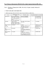
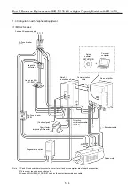
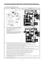
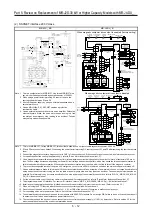
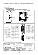
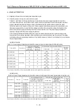
(2) MR-J4-DU_A_
(a) Power-on procedure
1) For the power supply wiring, make sure to use a magnetic contactor (L1/L2/L3) in the main circuit
power supply as shown in Section 2.1.
Configure so that the magnetic contactor is turned off at the same time as an alarm is generated
in the external sequence.
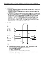
2) When the magnetic contactor drive output of the converter unit is enabled, turn on simultaneously
the control circuit power supply (L11/L12) of the converter unit and that of the drive unit. The main
circuit power supply is turned on automatically after the converter unit and drive unit start up.
When an external sequence controls the magnetic contactor, turn on the control circuit power
supply (L11/L12) of the converter unit and that of the drive unit at the same time as or before
turning on the main circuit power supply. If the main circuit power supply is not turned on, a
warning is displayed on the drive unit display. However, the warning disappears and operation
returns to normal when the main circuit power supply is turned on.
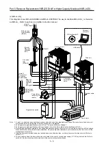
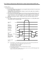
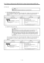
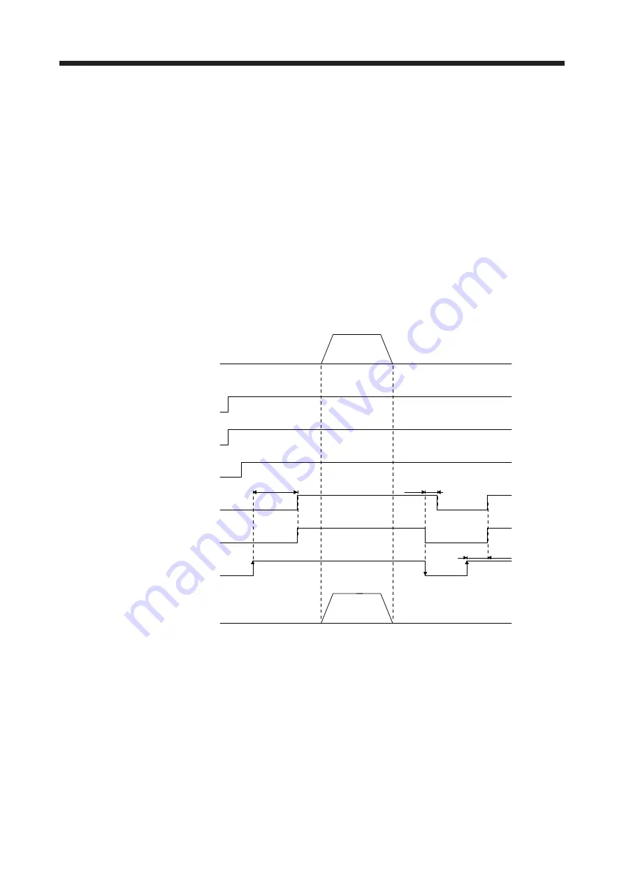
(b) Timing chart
ON
OFF
Main circuit
power supply
ON
OFF
SON (servo-on)
(95 ms)
ON
OFF
Base circuit
(3 s)
(Note 4)
Tb
ON
OFF
ON
OFF
MBR
(Electromagnetic
brake interlock)
0 r/min
Servo motor
speed
0 r/min
Position command
(Note 3)
(Note 2)
ON
OFF
(Note 1)
Converter unit
control circuit
power supply
Drive unit
control circuit
power supply
Note 1. When setting up an electromagnetic brake at customer's side, make up a sequence which will operate the
electromagnetic brake as follow using MBR (Electromagnetic brake interlock).
ON: Electromagnetic brake is not activated.
OFF: Electromagnetic brake is activated.
2. Give a position command after the external electromagnetic brake is released.
3. This is in position control mode.
4. In [Pr. PC16 Electromagnetic brake sequence output], set a delay time (Tb) from MBR (Electromagnetic brake
interlock) off to base circuit shut-off at a servo-off.
Summary of Contents for MELSERVO-J2-Super Series
Page 18: ...Part 1 Summary of MR J2S MR J2M Replacement 1 1 Part 1 Summary of MR J2S MR J2M Replacement ...
Page 31: ...Part 1 Summary of MR J2S MR J2M Replacement 1 14 MEMO ...
Page 109: ...Part 3 Review on Replacement of MR J2S _B_ with MR J4 _B_ 3 32 MEMO ...
Page 161: ...Part 4 Review on Replacement of MR J2S _CP_ CL_ with MR J4 _A_ RJ 4 52 MEMO ...
Page 239: ...Part 6 Review on Replacement of MR J2M with MR J4 6 20 MEMO ...
Page 240: ...Part 7 Common Reference Material 7 1 Part 7 Common Reference Material ...
Page 284: ...Part 7 Common Reference Material 7 45 Click Update Project ...
Page 342: ...Part 8 Review on Replacement of Motor 8 1 Part 8 Review on Replacement of Motor ...
Page 409: ...Part 8 Review on Replacement of Motor 8 68 MEMO ...
Page 461: ...Part 9 Review on Replacement of Optional Peripheral Equipment 9 52 MEMO ...
Page 462: ...Part 10 Startup Procedure Manual 10 1 Part 10 Startup Procedure Manual ...


