


[Appendix 1] Summary of MR-J4_B_-RJ020 + MR-J4-T20
Appendix 1-8
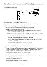
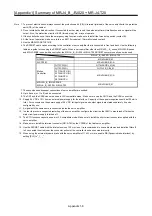
Note 1. To prevent electric shock, always connect the protective earth (PE) ( terminal (marked) of the servo amplifier to the protective
earth (PE) of the cabinet.
2. Do not mistake the diode direction. If connected the other way round, the servo amplifier will malfunction and no signal will be
output. Also, the protection circuits of EM1 (forced stop), etc., may not operate.
3. If the controller does not have the emergency stop function, make sure to install the forced stop switch (contact B).
4.
At the time of operation, make sure to turn on EM1 (forced stop). (Normally closed contact)
5. Use the MRZJW3-SETUP161E.
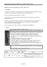
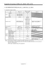
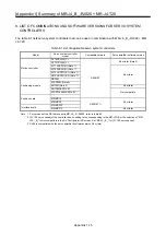
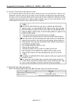
6. The SSCNET cable varies according to the controller or servo amplifier that is connected in front and back. Use the following
table as a guide for choosing the SSCNET cable. When a servo amplifier other than MR-J2S-_B_ series, MR-J2M-B series
and MR-J2-03B5 is used with a controller, the MR-J4-_B_-RJ020 + MR-J4-T20 SSCNET conversion unit cannot be used.
MR-J4-_B_-RJ020 + MR-J4-T20
QD75M MR-J2HBUS_M
A1SD75M MR-J2HBUS_M-A
Motion
Controller
Q172CPU(N) Q172J2BCBL_M(-B)
Q173CPU(N) Q173J2B_CBL_M
A171SHCPU (N)
,
A172SHCPU (N)
,
A173UHCPU
,
A273UHCPU
MR-J2HBUS_M-A
MR-J2S-_B_/MR-J2-03B5
MR-J4-_B_-RJ020 + MR-J4-T20
MR-J2HBUS_M
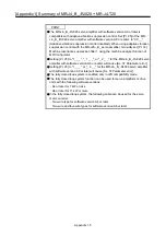
7. The second and subsequent connections of servo amplifier are omitted.
8. Up to 8 axes (n= 1 to 8) can be connected.
9. The CN1 and the CN1B cannot be used in J2S compatible mode. Make sure to cap the CN1A and the CN1B connectors.
10. Supply 24 V DC ± 10% from an external power supply for the interface. Capacity of these power supplies should be100 mA in
total. For convenience, the power supply of 24 V DC for input signals and output signals are stated separately, it can be
configured by one.
11.
A signal with the same name is connected inside the servo amplifier.
12. In order to prevent unexpected restarting of the servo amplifier, configure the circuit so that EM1 is also turned off when the
main circuit power supply is turned off.
13. The STO functions cannot be used in J2S compatible mode. Make sure to install the short-circuit connector supplied with the
servo amplifier.
14. Make sure to install the terminal connector (MR-A-TM) on the CN10B of the final servo amplifier.
15. Use the SSCNET cable with the total extension of 30 m or less. It is recommended to use cable clamps and data line filters (3
to 4 connected in series) near the connector pullout of the controller to enhance noise immunity.
16. When using the external dynamic brake with the servo amplifier of 11 kW or more, enable DB (Dynamic brake interlock) by
setting [Pr.2] to "_1_ _".
Summary of Contents for MELSERVO-J2-Super Series
Page 18: ...Part 1 Summary of MR J2S MR J2M Replacement 1 1 Part 1 Summary of MR J2S MR J2M Replacement ...
Page 31: ...Part 1 Summary of MR J2S MR J2M Replacement 1 14 MEMO ...
Page 109: ...Part 3 Review on Replacement of MR J2S _B_ with MR J4 _B_ 3 32 MEMO ...
Page 161: ...Part 4 Review on Replacement of MR J2S _CP_ CL_ with MR J4 _A_ RJ 4 52 MEMO ...
Page 239: ...Part 6 Review on Replacement of MR J2M with MR J4 6 20 MEMO ...
Page 240: ...Part 7 Common Reference Material 7 1 Part 7 Common Reference Material ...
Page 284: ...Part 7 Common Reference Material 7 45 Click Update Project ...
Page 342: ...Part 8 Review on Replacement of Motor 8 1 Part 8 Review on Replacement of Motor ...
Page 409: ...Part 8 Review on Replacement of Motor 8 68 MEMO ...
Page 461: ...Part 9 Review on Replacement of Optional Peripheral Equipment 9 52 MEMO ...
Page 462: ...Part 10 Startup Procedure Manual 10 1 Part 10 Startup Procedure Manual ...


