15. MR-J3W-0303BN6 SERVO AMPLIFIER
15 - 34
15.4.3 Wiring check
(1) Power supply system wiring
Before switching on the main circuit and control circuit power supplies, check the following items.
(a) Power supply system wiring
The power supplied to the power input terminals (24, 0, and PM) of the servo amplifier should satisfy the
defined specifications. (Refer to section 1.3.)
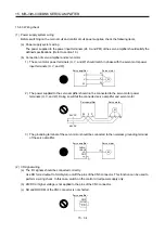
(b) Connection of servo amplifier and servo motor
1) The servo motor power terminals (U, V, and W) should match in phase with the servo motor power
input terminals (U, V, and W).
Servo amplifier
Servo motor
M
U
V
W
U
V
W
2) The power supplied to the servo amplifier should not be connected to the servo motor power
terminals (U, V, and W). Doing so will fail the connected servo amplifier and servo motor.
24
0
P
U
V
W
M
24VDC
48VDC
Servo amplifier
Servo motor
3) The grounding terminal of the servo motor should be connected to the noiseless grounding terminal
of the servo amplifier.
M
Servo amplifier
Servo motor
CNP
CNP2A/
CNP2B
(2) I/O signal wiring
(a) The I/O signals should be connected correctly.
Use DO forced output to forcibly turn on/off the pins of the CN3 connector. This function can be used to
perform a wiring check. In this case, switch on the control circuit power supply only.
(b) 24VDC or higher voltage is not applied to the pins of the CN3 connector.
(c) SD and DOCOM of the CN3 connector is not shorted.
Servo amplifier
DOCOM
SD
CN3
Summary of Contents for MELSERVO-J3W Series
Page 17: ...8 MEMO ...
Page 27: ...1 FUNCTIONS AND CONFIGURATION 1 10 MEMO ...
Page 87: ...4 STARTUP 4 14 MEMO ...
Page 117: ...5 PARAMETERS 5 30 MEMO ...
Page 129: ...6 GENERAL GAIN ADJUSTMENT 6 12 MEMO ...
Page 185: ...10 CHARACTERISTICS 10 8 MEMO ...
Page 241: ...11 OPTIONS AND AUXILIARY EQUIPMENT 11 56 MEMO ...
Page 274: ...13 USING A LINEAR SERVO MOTOR 13 25 1 2 3 4 ...


