12
1 FUNCTIONS AND CONFIGURATION
1.1 Description
1
FUNCTIONS AND CONFIGURATION
The following items are the same as those for MR-J4-_B_(-RJ). Refer to the section of the detailed explanation field for
details. "MR-J4-DU_B_" means "MR-CV_/MR-CR55K_/MR-J4-DU_(-RJ) Instruction Manual".
*1 Do not connect an external encoder to the CN2L connector of the MR-J4-DU_B4-RJ100 drive unit.
1.1
Description
This Instruction Manual describes MR-J4-DU_B4-RJ100 drive units and MR-CV55K4_ power regeneration converter units
compatible with parallel drive systems.
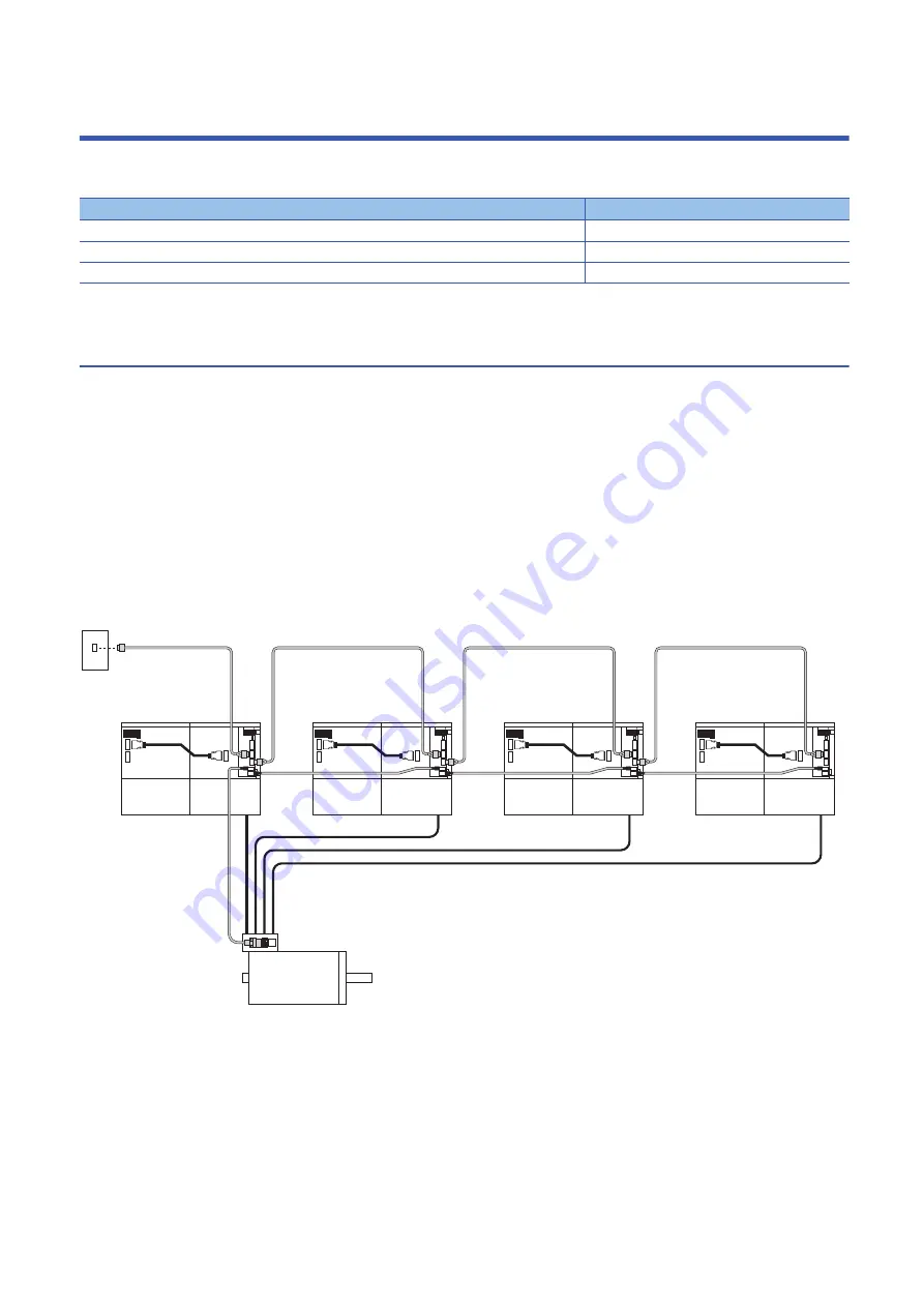
Parallel drive systems drive a servo motor with multiple MR-J4-DU_B4-RJ100 drive units and MR-CV55K4_ power
regeneration converter units connected. The encoder cables are wired by the daisy chain method. Delivering the encoder
information to all servo amplifiers, from encoder master servo amplifiers to encoder slave servo amplifiers, ensures reduced
wiring. A encoder distribution unit is not required.
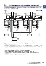
The following shows a system that drives a servo motor with four MR-J4-DU_B4-RJ100 drive units and four MR-CV55K4_
power regeneration converter units connected. For the number of drive units required to be connected to one servo motor,
refer to the following.
Page 13 Combinations of power regeneration converter units, drive units, and servo motors
Item
Detailed explanation
Function block diagram
MR-J4-DU_B_ section 3.1
Standard specifications
MR-J4-DU_B_ section 1.4
Structure
MR-J4-DU_B_ sections 3.2 and 5.1
Encoder slave servo amplifier 3
Encoder slave servo amplifier 2
Encoder slave servo amplifier 1
SSCNET III/H
Servo system
controller
Power
regeneration
converter unit 1
Drive
unit 1
Power
regeneration
converter unit 2
Drive
unit 2
Power
regeneration
converter unit 3
Drive
unit 3
Power
regeneration
converter unit 4
Drive
unit 4
Encoder master servo amplifier
Servo motor
Summary of Contents for Melservo-J4 MR-J4-DU*B4-RJ100 Series
Page 2: ......
Page 75: ...9 USING STO FUNCTION 73 9 MEMO ...
Page 81: ...11 APPENDIX 11 1 Analog monitor 79 11 MEMO ...
Page 85: ......


