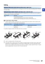
350
10 USING A LINEAR SERVO MOTOR
10.2 Startup [G] [WG]
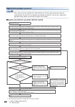
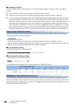
Magnetic pole detection procedure
When using a controller manufactured by Mitsubishi Electric, the servo parameter setting values are
overwritten from the controller. Once magnetic pole detection is complete, note down the changed servo
parameter setting values, and set the same values in the controller.
■
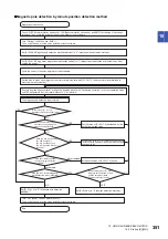
Magnetic pole detection by position detection method
*1 For the incremental system, the setting of [Pr. PL01] is not required.
NO
YES
YES
NO
YES
NO
Magnetic pole detection
Set [Pr. PL08.0 Magnetic pole detection method selection] to "0" (position detection method).
Set [Pr. PL01.0 Servo motor magnetic pole detection selection] to "1" (Magnetic pole detection at initial servo-on after cycling the
power).
*1
Set [Pr. PL09 Magnetic pole detection - Voltage level] to "10" as a guide value.
Execute "positive direction travel" or "negative direction travel" with "Positioning operation" in the test operation mode on MR
Configurator2. Set the travel distance to "0" at this time.
The magnetic pole detection is performed.
Is [Pr. PL09] the final value?
Perform one of the following
operations: alarm reset, servo
amplifier power cycling, or software
reset.
Has [AL. 027 Initial magnetic
pole detection error] occurred?
Increase the value of [Pr. PL09] by
five.
Have [AL. 032 Overcurrent],
[AL. 050 Overload 1],
[AL. 051 Overload 2], and
[AL. 0E1 Overload warning 1]
occurred?
Cycle the power of the servo amplifier
or reset the software.
Set approximately 70 % of the value
set for [Pr. PL09] as the final setting
value. If [AL. 027] occurs with this
value, specify a value intermediate
between the value set at [AL. 0E1]
and the value set at [AL. 027] as the
final setting value.
Perform one of the following
operations: alarm reset, servo
amplifier power cycling, or software
reset.
Set [Pr. PL01.0] to "0" (Magnetic pole detection disabled).
*1
End
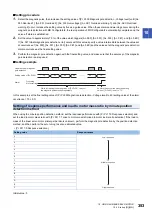
Check if LSP (Forward rotation stroke end), LSN (Reverse rotation stroke end), and EM2 (Forced stop 2) have been turned on.
Then, cycle the power of the servo amplifier or reset software.
Turn "ON (up)" the DIP switch (SW3-1).
Then, cycle the power of the servo amplifier or reset software.
Cycle the power of the servo amplifier or reset software.
Turn "OFF (down)" the DIP switch (SW3-1).
Then, cycle the power of the servo amplifier or reset software.
Summary of Contents for MELSERVO-J5 MR-J5-G Series
Page 2: ......
Page 473: ...12 USING A FULLY CLOSED LOOP SYSTEM 12 7 Absolute position detection system 471 12 MEMO ...
Page 477: ......

