246
6 OPTIONS AND PERIPHERAL EQUIPMENT
6.17 MR-J3-D05 safety logic unit
LED display
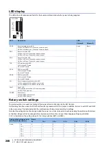
The LEDs show I/O statuses and faults for the A-axis and B-axis and whether power is being supplied.
Rotary switch settings
The rotary switches are used for shutting off the power after a control stop by the SS1 function.
Set the delay time from when the STO shut-off switch is pressed until STO is output. In addition, be sure to set SW1 and SW2
to the same value. The table below lists the combinations of delay times according to settings.
Note that the settings cannot be changed while the power is on. Also, take actions such as sealing the switches with stickers
so that the settings will not be changed after shipment, and inform the end user that changing settings is prohibited.
0 to F in the table are the setting values for the rotary switches (SW1 and SW2).
LED
Description
LED
Column A
Column B
SRES
Shut-off release monitor LED
Off: Shut-off release is off. (The switch contact is open.)
On: Shut-off release is on. (The switch contact is closed.)
A-axis
B-axis
SDI1
Shut-off 1 monitor LED
Off: Shut-off 1 is off. (The switch contact is closed.)
On: Shut-off 1 is on. (The switch contact is open.)
SDI2
Shut-off 2 monitor LED
Off: Shut-off 2 is off. (The switch contact is closed.)
On: Shut-off 2 is on. (The switch contact is open.)
TOF
STO status monitor LED
Off: Not in the STO state.
On: In the STO state.
SDO1
SDO1 monitor LED
Off: Not in the STO state.
On: In the STO state.
SDO2
SDO2 monitor LED
Off: Not in the STO state.
On: In the STO state.
SW
Shut-off delay setting check monitor LED
Off: The settings of SW1 and SW2 do not match.
On: The settings of SW1 and SW2 are the same.
FAULT
FAULT LED
Off: Operating as specified. (STO monitoring state)
On: FAULT has occurred.
POWER
Power supply
Off: MR-J3-D05 power shut-off.
On: MR-J3-D05 power on.
Rotary switch settings and A-
axis/B-axis delay time [s]
B-axis
0 s
1.4 s
2.8 s
5.6 s
9.8 s
30.8 s
A-axis
0 s
0
1
2
3
4
1.4 s
5
6
7
2.8 s
8
9
A
5.6 s
B
C
9.8 s
D
E
30.8 s
F
MR-J3-D05
SRES
A
B
SDI1
SDI2
TOF
SDO1
SDO2
SW
FAULT
POWER
Summary of Contents for Melservo-J5 MR-J5 Series
Page 2: ......
Page 441: ...12 USING A FULLY CLOSED LOOP SYSTEM 12 7 Absolute position detection system 439 12 MEMO ...
Page 445: ......

