8 USING STO FUNCTION
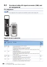
8.2 Functional safety I/O signal connector (CN8) and pin assignments
291
8
Signals and STO status
The following table shows the status of TOFB and STO for when STO1 and STO2 are ON (closed) or OFF (open) while the
power is turned on in an operation with no alarms or warnings.
*1 Between TOFB1 and TOFB2 is off, but the servo amplifier is in the STO state.
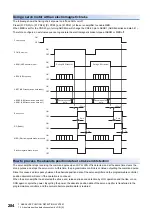
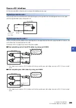
Test pulse of STO input signal
Set the test pulse off time inputted from outside to 1 ms or less.
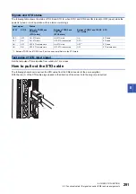
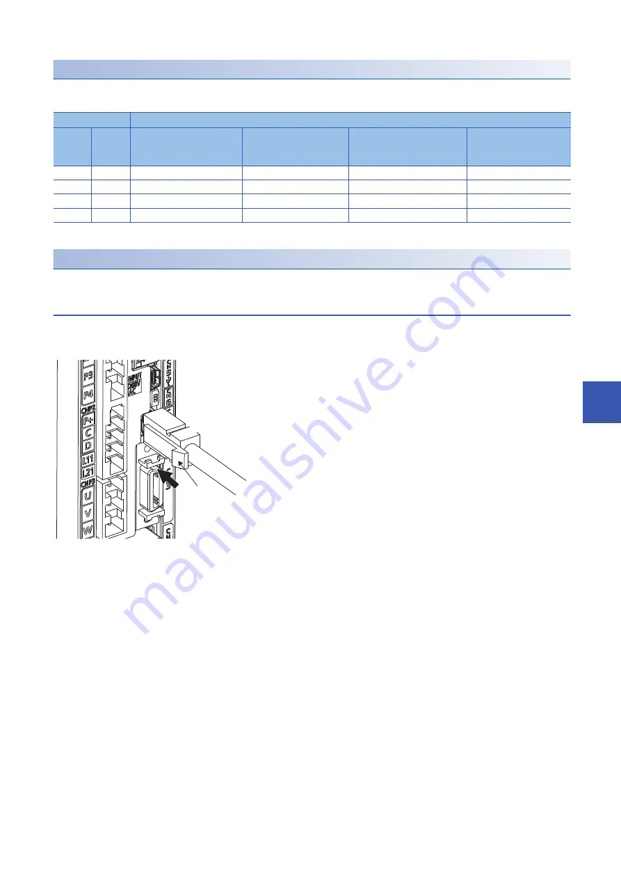
How to pull out the STO cable
The following shows how to pull out the STO cable from the CN8 connector of the servo amplifier.
With the clip (1) of the STO cable plug pressed in the direction of the arrow, hold the plug (2) and pull out.
Input signal
Status
STO1
STO2
Between TOFB1 and
TOFCOM
(STO1 state)
Between TOFB2 and
TOFCOM
(STO2 state)
Between TOFB1 and TOFB2
(STO state)
STO
OFF
OFF
ON: STO state
ON: STO state
ON
STO state
OFF
ON
ON: STO state
OFF: STO release state
OFF
STO state
ON
OFF
OFF: STO release state
ON: STO state
OFF
STO state
ON
ON
OFF: STO release state
OFF: STO release state
OFF
STO release state
(1)
(2)
Summary of Contents for Melservo-J5 MR-J5 Series
Page 2: ......
Page 441: ...12 USING A FULLY CLOSED LOOP SYSTEM 12 7 Absolute position detection system 439 12 MEMO ...
Page 445: ......

