52
3 SIGNALS AND WIRING
3.2 Example I/O signal connections
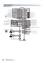
*1 To prevent an electric shock, connect the protective earth (PE) terminal (the terminal marked with the
symbol) of the servo amplifier
to the protective earth (PE) of the cabinet.
*2 Connect the diode in the correct direction. If it is connected reversely, the servo amplifier may malfunction and not output signals,
disabling protective circuits such as EM2 (Forced stop 2).
*3 If the controller does not have the forced stop function, install a forced stop 2 switch (normally closed contact).
*4 When starting operation, turn on EM2 (Forced stop 2), LSP (Forward rotation stroke end), and LSN (Reverse rotation stroke end)
(normally closed contact). If FLS (Upper stroke limit) and RLS (Lower stroke limit) are used via a controller, wiring LSP and LSN is
unnecessary. In that case, set [Pr. PD41].
*5 Use SW1DNC-MRC2-_.
*6 Supply 24 V DC ± 10 % to interfaces from outside. The total current capacity of these power supplies is 350 mA maximum for the MR-
J5W2-_G_ and 450 mA maximum for the MR-J5W3-_G_.
The amperage will not exceed 350 mA (MR-J5W2-_G_) and 450 mA (MR-J5W3-_G_) when all I/O signals are used. Reducing the
number of I/O points decreases the current capacity. For the amperage required for interfaces, refer to the following.
Page 93 Digital input interface DI-1
Although the diagram shows the input signal and the output signal each using a separate 24 V DC power supply for illustrative purposes,
the system can be configured to use a single 24 V DC power supply.
*7 If no alarm is occurring, CALM (AND malfunction) is on (normally closed contact).
*8 In the initial setting, CINP (AND in-position) is assigned to this pin. The device of the pin can be changed with [Pr. PD08].
*9 The devices of these pins can be changed with servo parameters ([Pr. PD07] and [Pr. PD09]).
*10 The devices of these pins can be changed with servo parameters ([Pr. PD03] to [Pr. PD05]).
*11 To prevent an unexpected restart of the servo amplifier, configure a circuit that turns off EM2 when the main circuit power supply is
turned off.
*12 If not using the STO function, attach the short-circuit connector that came with the servo amplifier.
*13 This pin cannot be used on 2-axis servo amplifiers.
*14 The diagram is for 3-axis servo amplifiers.
*15 This signal cannot be used on 3-axis servo amplifiers.
*16 If installing an external brake mechanism for a linear servo motor or direct drive motor, use MBR (Electromagnetic brake interlock).
Summary of Contents for Melservo-J5 MR-J5 Series
Page 2: ......
Page 441: ...12 USING A FULLY CLOSED LOOP SYSTEM 12 7 Absolute position detection system 439 12 MEMO ...
Page 445: ......


