56
3 SIGNALS AND WIRING
3.3 Explanation of power supply system
Power-on procedure [G] [WG]
Signals such as output signals may be unstable at power-on.
Power-on procedure
1.
Wire the power supply using a magnetic contactor between the power supply and the main circuit power supply (L1/L2/
L3) of a servo amplifier by referring to the following section. Switch off the magnetic contactor as soon as an alarm
occurs.
Page 33 Example power circuit connections
2.
Switch on the control circuit power supply (L11 and L21) simultaneously with the main circuit power supply or before
switching on the main circuit power supply. If the control circuit power supply is turned on and the servo-on command is
transmitted while the main circuit power supply is off, [AL. 0E9 Main circuit off warning] will occur. Turning on the main
circuit power supply stops the warning and starts the operation properly.
3.
When the main circuit power supply is switched on, the servo amplifier will receive the servo-on command after startup
and initial network communication.
The startup time for 1-axis servo amplifiers is 2.5 s to 3.5 s, and the startup time for multi-axis servo amplifiers is 3.5 s to 4.0 s.
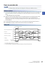
Timing chart
*1 For a linear servo system, this time is 2 s longer.
*2 The time will be longer in the magnetic pole detection of a linear servo motor and direct drive motor.
ON
OFF
ON
OFF
ON
OFF
ON
OFF
100 ms
*2
5 ms
100 ms
*2
5 ms
10 ms
Servo-on command accepted
(Startup time +
network initial
communication time)
*1
Main/control circuit power supply
Base circuit
Servo-on command
(from controller)
Servo-on (RD: Ready)
No alarm (ON)
ALM (Malfunction)
Alarm (OFF)
Summary of Contents for Melservo-J5 MR-J5 Series
Page 2: ......
Page 441: ...12 USING A FULLY CLOSED LOOP SYSTEM 12 7 Absolute position detection system 439 12 MEMO ...
Page 445: ......


