3 SIGNALS AND WIRING
3.3 Explanation of power supply system
61
3
Connecting wires
■
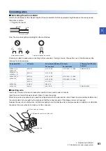
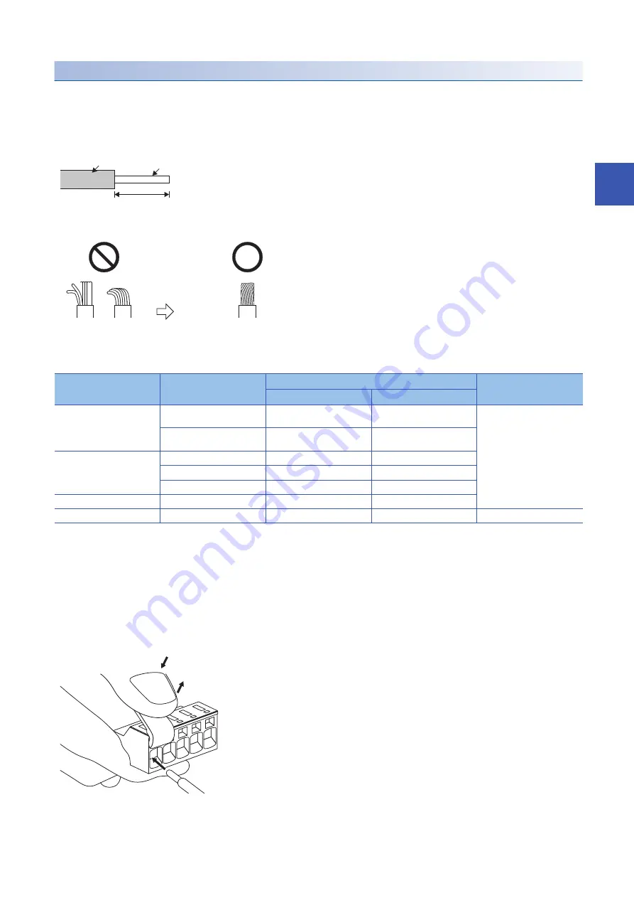
Fabricating the wire insulator
Refer to the following for the stripped length of the wire insulator. Set the appropriate length based on the wire type and
fabrication condition.
Twist the core wires lightly and straighten them as follows.
A ferrule can also be used when connecting to the connectors. If using a ferrule, choose from one of the ferrules and the
crimping tools shown below.
■
Inserting wire
Insert only one wire or ferrule into each wire insertion hole on each power connector.
Insert the open tool as follows and push it down to open the spring.
While the open tool is pushed down, insert the stripped wire into the wire insertion hole. Check the wire insertion depth so that
the wire insulator is not caught by the spring and that the conductive part of the stripped wire is not exposed.
Release the open tool to fix the wire. Pull the wire lightly to confirm that the wire is surely connected. In addition, confirm that
the ends of the core wires do not stick out of the connector.
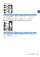
Servo amplifier
Wire size
Ferrule model (Phoenix Contact)
Crimping tool (Phoenix
Contact)
For one wire
For two wires
MR-J5-10_ to
MR-J5-100_
MR-J5W2-_G_
MR-J5W3-_G_
AWG 16
AI 1,5 -10 BK
AI-TWIN 2X 1,5 -10 BK
CRIMPFOX-ZA3
AWG 14
AI 2,5 -10 BU
MR-J5-200_ to
MR-J5-350_
AWG 16
AI 1,5 -10 BK
AI-TWIN 2X 1,5 -10 BK
AWG 14
AI 2,5 -10 BU
AI-TWIN 2X 2,5 -10 BU
AWG 12
AI 4 -10 GY
MR-J5-500_
AWG 10
Al6-12 YE
MR-J5-700_
AWG 8
Al10-12 RD
CRIMPFOX-25R
Insulator
Core
Stripped length
Twist and straighten the strands.
Loose and bent strands
(1) Push down the open tool.
(3) Release the open tool to fix the wire.
(2) Insert the wire.
Summary of Contents for Melservo-J5 MR-J5 Series
Page 2: ......
Page 441: ...12 USING A FULLY CLOSED LOOP SYSTEM 12 7 Absolute position detection system 439 12 MEMO ...
Page 445: ......

