290
8 USING STO FUNCTION
8.2 Functional safety I/O signal connector (CN8) and pin assignments
8.2
Functional safety I/O signal connector (CN8) and
pin assignments
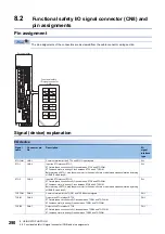
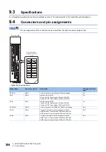
Pin assignment
The pin assignments of the connectors are as viewed from the cable connector wiring section.
Signal (device) explanation
I/O device
Signal
name
Connector pin
No.
Description
I/O
signal
interface
type
STOCOM
CN8-3
Common terminal for the STO1 and STO2 input signals
DI-1
STO1
CN8-4
Input the STO status of STO1.
STO state (base circuit shut-off): Open between STO1 and STOCOM.
STO release state (in driving): Close between STO1 and STOCOM.
Before turning off STO1, stop the servo motor in the servo-off state or with forced stop deceleration by turning
off EM2 (Forced stop 2).
DI-1
STO2
CN8-5
Input the STO status of STO2.
STO state (base circuit shut-off): Open between STO2 and STOCOM.
STO release state (in driving): Close between STO2 and STOCOM.
Before turning off STO2, stop the servo motor in the servo-off state or with forced stop deceleration by turning
off EM2 (Forced stop 2).
DI-1
TOFCOM
CN8-8
Common terminal for the TOFB1 and TOFB2 output signals
DO-1
TOFB1
CN8-6
Outputs the STO status of STO1.
STO state (base circuit shut-off): Closed between TOFB1 and TOFCOM.
STO release state (in driving): Open between TOFB1 and TOFCOM.
DO-1
TOFB2
CN8-7
Outputs the STO status of STO2.
STO state (base circuit shut-off): Closed between TOFB2 and TOFCOM.
STO release state (in driving): Open between TOFB2 and TOFCOM.
DO-1
CN8
TOFB2
STO2
TOFB1
STO1
STOCOM
2
1
4
3
6
5
8
7
TOFCOM
Servo amplifier
Functional safety
I/O signal connector
Summary of Contents for Melservo-J5 MR-J5 Series
Page 2: ......
Page 441: ...12 USING A FULLY CLOSED LOOP SYSTEM 12 7 Absolute position detection system 439 12 MEMO ...
Page 445: ......

