366
11 USING A DIRECT DRIVE MOTOR
11.2 Startup [G] [WG]
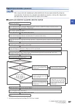
*1 Use MR Configurator2.
*2 In the absolute position detection system, turn on the Z-phase pulse of the direct drive motor while the servo amplifier power is on, and
then cycle the power of the servo amplifier. Cycling the power confirms the absolute position. Without this operation, the absolute
position will not be restored properly, and a warning will occur at the controller.
*3 If the Z-phase pulse of the direct drive motor can be turned on manually, the Z-phase pulse does not have to be turned on by the
magnetic pole detection or the JOG operation.
For this operation, connect the direct drive motor encoder and the servo amplifier, and turn on only the control circuit power supply of the
servo amplifier (L11/L21) (turn off the main circuit power supply L1/L2/L3). Ensure the safety at this time.
*4 After the servo amplifier is connected to the direct drive motor with an encoder cable, [AL. 025 Absolute position erased] occurs at the
initial power-on. Cancel the alarm by turning off/on the power.
Magnetic pole detection
Precautions
• The magnetic pole detection is not required for the configured absolute position detection system where the Z-phase pulse
of the direct drive motor manufactured by Mitsubishi Electric can be turned on manually. For this operation, connect the
direct drive motor encoder and the servo amplifier, and turn on the control circuit power supply of the servo amplifier.
Ensure the safety at this time.
• For the magnetic pole detection of vertical axis with direct drive motors, refer to the following.
Direct Drive Motor User's Manual
Outline of magnetic pole detection
Before the positioning operation of the direct drive motor, perform the magnetic pole detection.
When starting up the equipment, use the test operation mode (positioning operation) of MR Configurator2.
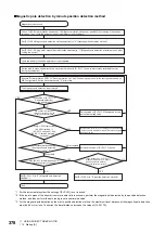
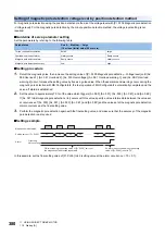
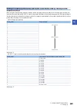
The magnetic pole detection includes the position detection method and minute position detection method. Each method has
advantages and disadvantages. Refer to the following for the characteristics of each method.
Page 317 Outline of magnetic pole detection
Select a magnetic pole detection method suitable for the usage.
In the initial value, the position detection method is selected.
Precautions on magnetic pole detection
• For the magnetic pole detection, the direct drive motor automatically starts to move simultaneously with turning-on of the
servo-on command.
• If the magnetic pole detection is not executed properly, the direct drive motor may operate unexpectedly.
• Establish the machine configuration to use LSP (Forward rotation stroke end) and LSN (Reverse rotation stroke end). The
machine may be damaged due to a collision without LSP and LSN.
• Assign LSP and LSN, and perform the magnetic pole detection also in the torque mode.
• At the magnetic pole detection, whether the direct drive motor moves in the positive or negative direction is unpredictable.
• Depending on the setting value of [Pr. PL09 Magnetic pole detection - Voltage level], an overload, overcurrent, magnetic
pole detection alarm, or others may occur.
• When performing the positioning operation from a controller, use the sequence which confirms the normal completion of the
magnetic pole detection and the servo-on status, then outputs the positioning command. If the controller outputs the
positioning command before RD (Ready) turns on, the command may not be accepted or an alarm may occur.
• For the machine whose friction becomes 30 % or more of the continuous thrust, the direct drive motor may not operate
properly after the magnetic pole detection.
• For the horizontal shaft of the machine whose unbalanced thrust becomes 20 % or more of the continuous thrust, the direct
drive motor may not operate properly after the magnetic pole detection.
• The magnetic pole detection may fail if performed simultaneously with multiple axes connected to each other (e.g. a
tandem configuration). Perform the magnetic pole detection for each axis. At this time, set the axes for which the magnetic
pole detection is not performed to servo-off.
• During the magnetic pole detection, the value of [Pr. PE47 Unbalanced torque offset] is regarded as "0".
Summary of Contents for Melservo-J5 MR-J5 Series
Page 2: ......
Page 441: ...12 USING A FULLY CLOSED LOOP SYSTEM 12 7 Absolute position detection system 439 12 MEMO ...
Page 445: ......


