background image

MR-J5-G/MR-J5W-G
User's Manual
(Object Dictionary)

-MR-J5-_G_
-MR-J5W_-_G

Mitsubishi Electric AC Servo System

Summary of Contents for MELSERVO J5 Series

Page 1: ...MR J5 G MR J5W G User s Manual Object Dictionary MR J5 _G_ MR J5W_ _G Mitsubishi Electric AC Servo System ...

Page 2: ......

Page 3: ... Please follow the instructions of both levels because they are important to personnel safety Forbidden actions and required actions are indicated by the following diagrammatic symbols In this manual precautions for hazards that can lead to property damage instructions for other functions and other information are shown separately in the POINT area After reading this manual keep it accessible to t...

Page 4: ...efore wiring To prevent an electric shock connect the protective earth PE terminal of the servo amplifier to the protective earth PE of the cabinet then connect the grounding lead wire to the ground To prevent an electric shock do not touch the conductive parts WARNING To prevent an electric shock do not operate the switches with wet hands WARNING To prevent an electric shock do not operate the sw...

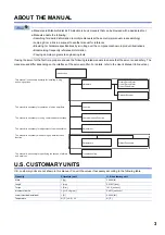
Page 5: ...oduction U S CUSTOMARY UNITS U S customary units are not shown in this manual Convert the values if necessary according to the following table Quantity SI metric unit U S customary unit Mass 1 kg 2 2046 lb Length 1 mm 0 03937 inch Torque 1 N m 141 6 oz inch Moment of inertia 1 10 4 kg m2 5 4675 oz inch2 Load thrust load axial load 1 N 0 2248 lbf Temperature N C 9 5 32 N F Rotary Servo Motor Linear...

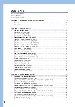
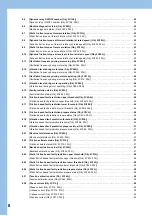
Page 6: ...9 Restore all default parameters Obj 1011h 01h 19 2 8 Identity Object Obj 1018h 19 Identity Object Obj 1018h 00h 19 Vendor ID Obj 1018h 01h 19 Product Code Obj 1018h 02h 20 Revision Number Obj 1018h 03h 20 Serial Number Obj 1018h 04h 20 2 9 Version number Obj 67FEh 20 Version number Obj 67FEh 00h 20 CHAPTER 3 PDO Mapping Objects 21 3 1 1st Receive PDO Mapping Obj 1600h 21 1st Receive PDO Mapping O...

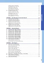
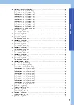
Page 7: ...bj 2001h PA44 Obj 202Ch 34 5 2 PB01 Obj 2081h PB92 Obj 20DCh 34 5 3 PC01 Obj 2101h PC90 Obj 215Ah 34 5 4 PD01 Obj 2181h PD72 Obj 21C8h 34 5 5 PE01 Obj 2201h PE88 Obj 2258h 34 5 6 PF01 Obj 2281h PF99 Obj 22E3h 34 5 7 PL01 Obj 2401h PL72 Obj 2448h 34 5 8 PT01 Obj 2481h PT90 Obj 24DAh 34 5 9 PN01 Obj 2581h PN32 Obj 25A0h 34 5 10 PV group parameters Obj 2691h 35 PV group parameters Obj 2691h 00h 35 PV...

Page 8: ... Cumulative feedback pulses Obj 2B01h 00h 42 7 2 Servo motor speed Obj 2B02h 42 Servo motor speed Obj 2B02h 00h 42 7 3 Droop pulses Obj 2B03h 42 Droop pulses Obj 2B03h 00h 42 7 4 Cumulative command pulses Obj 2B04h 42 Cumulative command pulses Obj 2B04h 00h 42 7 5 Command pulse frequency Obj 2B05h 43 Command pulse frequency Obj 2B05h 00h 43 7 6 Regenerative load ratio Obj 2B08h 43 Regenerative loa...

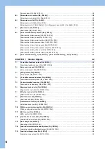
Page 9: ...ation detection frequency Obj 2B27h 00h 48 7 27 Number of tough drive operations Obj 2B28h 48 Number of tough drive operations Obj 2B28h 00h 48 7 28 Internal temperature of amplifier Obj 2B2Ah 48 Internal temperature of amplifier Obj 2B2Ah 00h 48 7 29 Unit power consumption Obj 2B2Dh 48 Unit power consumption Obj 2B2Dh 00h 48 7 30 Unit total power consumption Obj 2B2Eh 48 Unit total power consumpt...

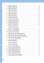
Page 10: ...Obj 2C2Ah 56 Friction based fault prediction upper threshold Obj 2C2Ah 00h 56 8 17 Friction based fault prediction lower threshold Obj 2C2Bh 56 Friction based fault prediction lower threshold Obj 2C2Bh 00h 56 8 18 Friction based fault prediction prepare status Obj 2C2Ch 56 Friction based fault prediction prepare status Obj 2C2Ch 00h 56 8 19 Vibration based fault prediction threshold Obj 2C2Dh 56 V...

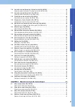
Page 11: ... 00h 63 8 35 Control DI 6 Obj 2D06h 63 Control DI 6 Obj 2D06h 00h 63 8 36 Control DI 7 Obj 2D07h 63 Control DI 7 Obj 2D07h 00h 63 8 37 Control DI 8 Obj 2D08h 64 Control DI 8 Obj 2D08h 00h 64 8 38 Control DI 9 Obj 2D09h 64 Control DI 9 Obj 2D09h 00h 64 8 39 Control DI 10 Obj 2D0Ah 64 Control DI 10 Obj 2D0Ah 00h 64 8 40 Supported Status DO Obj 2D10h 65 Supported Status DO Obj 2D10h 00h 65 Supported ...

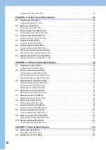
Page 12: ... Obj 2D36h 00h 72 8 56 Scale ABS counter Obj 2D37h 72 Scale ABS counter Obj 2D37h 00h 72 8 57 Scale measurement encoder resolution Obj 2D38h 73 Scale measurement encoder resolution Obj 2D38h 00h 73 8 58 Scale measurement encoder reception status Obj 2D3Ch 73 Scale measurement encoder reception status Obj 2D3Ch 00h 73 8 59 Servo motor serial number Obj 2D46h 73 Servo motor serial number Obj 2D46h 0...

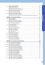
Page 13: ...indow Obj 6065h 00h 87 10 4 Following error time out Obj 6066h 87 Following error time out Obj 6066h 00h 87 10 5 Position window Obj 6067h 88 Position window Obj 6067h 00h 88 10 6 Position window time Obj 6068h 88 Position window time Obj 6068h 00h 88 10 7 Positioning option code Obj 60F2h 88 Positioning option code Obj 60F2h 00h 88 10 8 Following error actual value Obj 60F4h 89 Following error ac...

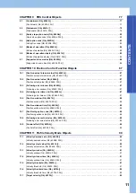
Page 14: ... 13 2 Position range limit Obj 607Bh 96 Position range limit Obj 607Bh 00h 96 Min position range limit Obj 607Bh 01h 96 Max position range limit Obj 607Bh 02h 96 13 3 Software position limit Obj 607Dh 97 Software position limit Obj 607Dh 00h 97 Min position limit Obj 607Dh 01h 97 Max position limit Obj 607Dh 02h 97 13 4 Max profile velocity Obj 607Fh 98 Max profile velocity Obj 607Fh 00h 98 13 5 M...

Page 15: ...ant Obj 6092h 106 Feed constant Obj 6092h 00h 107 Feed Obj 6092h 01h 107 Shaft revolutions Obj 6092h 02h 107 15 5 SI unit position Obj 60A8h 107 SI unit position Obj 60A8h 00h 107 15 6 SI unit velocity Obj 60A9h 107 SI unit velocity Obj 60A9h 00h 107 15 7 SI unit acceleration Obj 60AAh 108 SI unit acceleration Obj 60AAh 00h 108 CHAPTER 16 Touch Probe Function Objects 109 16 1 Touch probe function ...

Page 16: ...Optional application FE Objects 114 17 1 Digital inputs Obj 60FDh 114 Digital inputs Obj 60FDh 00h 114 CHAPTER 18 Cyclic Synchronous Position Mode Objects 118 18 1 Position offset Obj 60B0h 118 Position offset Obj 60B0h 00h 118 18 2 Velocity offset Obj 60B1h 118 Velocity offset Obj 60B1h 00h 118 18 3 Torque offset Obj 60B2h 118 Torque offset Obj 60B2h 00h 118 REVISIONS 120 WARRANTY 121 TRADEMARKS ...

Page 17: ...tes the object size Access Indicates whether the object can be read or written RO Only reading is available RW Reading and writing are available Mapping Indicates whether the object can be mapped in cyclic communication Impossible The object cannot be mapped to TXPDO or RXPDO TXPDO The object can be mapped to TXPDO RXPDO The object can be mapped to RXPDO TXPDO RXPDO The object can be mapped to TXP...

Page 18: ...16 1 SUMMARY OF OBJECT DICTIONARY 1 1 Structure MEMO ...

Page 19: ...r Device Name Obj 1008h 00h Description The model name of the servo amplifier is returned Ex If MR J5 10G is used the model name is returned as shown below MR J5 10G Empty spaces after the model name are filled with blank spaces to make the name 32 characters long Data Type Access Mapping Default Range Units Save Parameter U32 RO Impossible 00020192h 00020192h fixed Impossible Bit Symbol Descripti...

Page 20: ...rameters that can be stored in the non volatile memory The descriptions of the read values are as follows Data Type Access Mapping Default Range Units Save Parameter VISIBLE STRING RO Impossible Impossible Data Type Access Mapping Default Range Units Save Parameter VISIBLE STRING RO Impossible Impossible Data Type Access Mapping Default Range Units Save Parameter U8 RO Impossible Impossible Defaul...

Page 21: ...ervo amplifier is used the servo parameters of all axes are initialized The read value is always 1 initializing values 2 8 Identity Object Obj 1018h Identity Object Obj 1018h 00h Description The total number of Sub Indexes is returned Vendor ID Obj 1018h 01h Description The vendor ID of the servo amplifier is returned Data Type Access Mapping Default Range Units Save Parameter U8 RO Impossible Imp...

Page 22: ...is returned 2 9 Version number Obj 67FEh Version number Obj 67FEh 00h Description The version number of the supported CiA 402 profile is returned Data Type Access Mapping Default Range Units Save Parameter U32 RO Impossible 00000000h to FFFFFFFFh Impossible Data Type Access Mapping Default Range Units Save Parameter U32 RO Impossible 00000000h to FFFFFFFFh Impossible Data Type Access Mapping Defau...

Page 23: ...h Description Indicates the total number of objects included in PDO To set a value in an object of Sub Index 1 or later write 00h in the object After setting the value for objects of Sub Index 1 or later write the total number of objects mapped to PDO Data Type Access Mapping Default Range Units Save Parameter U8 RW Impossible 00h to 20h Impossible PDO mapping ...

Page 24: ...ed Object 006 60400010h 07h Mapped Object 007 60E00010h 08h Mapped Object 008 60E10010h 09h Mapped Object 009 60710010h 0Ah Mapped Object 010 2D200020h 0Bh Mapped Object 011 2D010010h 0Ch Mapped Object 012 2D020010h 0Dh Mapped Object 013 2D030010h 0Eh Mapped Object 014 2D040010h 0Fh Mapped Object 015 2D050010h 10h Mapped Object 016 00000010h 11h Mapped Object 017 00000000h 12h Mapped Object 018 00...

Page 25: ...on Indicates the total number of objects included in PDO To set a value in an object of Sub Index 1 or later write 00h in the object After setting the value for objects of Sub Index 1 or later write the total number of objects mapped to PDO Data Type Access Mapping Default Range Units Save Parameter U8 RW Impossible 00h to 20h Impossible PDO mapping ...

Page 26: ...ed Object 006 2D040010h 07h Mapped Object 007 00000000h 08h Mapped Object 008 00000000h 09h Mapped Object 009 00000000h 0Ah Mapped Object 010 00000000h 0Bh Mapped Object 011 00000000h 0Ch Mapped Object 012 00000000h 0Dh Mapped Object 013 00000000h 0Eh Mapped Object 014 00000000h 0Fh Mapped Object 015 00000000h 10h Mapped Object 016 00000000h 11h Mapped Object 017 00000000h 12h Mapped Object 018 00...

Page 27: ...ion The total number of objects included in PDO is returned To set a value in an object of Sub Index 1 or later write 00h in the object After setting the value for objects of Sub Index 1 or later write the total number of objects mapped to PDO Data Type Access Mapping Default Range Units Save Parameter U8 RW Impossible 00h to 20h Impossible PDO mapping ...

Page 28: ...ped Object 006 60F40020h 07h Mapped Object 007 60410010h 08h Mapped Object 008 00000010h 09h Mapped Object 009 60770010h 0Ah Mapped Object 010 2D110010h 0Bh Mapped Object 011 2D120010h 0Ch Mapped Object 012 2D130010h 0Dh Mapped Object 013 2D140010h 0Eh Mapped Object 014 2D150010h 0Fh Mapped Object 015 2A410020h 10h Mapped Object 016 2D210020h 11h Mapped Object 017 2D220010h 12h Mapped Object 018 0...

Page 29: ...ion The total number of objects included in PDO is returned To set a value in an object of Sub Index 1 or later write 00h in the object After setting the value for objects of Sub Index 1 or later write the total number of objects mapped to PDO Data Type Access Mapping Default Range Units Save Parameter U8 RW Impossible 00h to 20h Impossible PDO mapping ...

Page 30: ...ped Object 006 2D110010h 07h Mapped Object 007 2D140010h 08h Mapped Object 008 60770010h 09h Mapped Object 009 606C0020h 0Ah Mapped Object 010 2A410020h 0Bh Mapped Object 011 00000000h 0Ch Mapped Object 012 00000000h 0Dh Mapped Object 013 00000000h 0Eh Mapped Object 014 00000000h 0Fh Mapped Object 015 00000000h 10h Mapped Object 016 00000000h 11h Mapped Object 017 00000000h 12h Mapped Object 018 0...

Page 31: ...or the detection of RPDO receive errors This object is available when an object set in PDO Assignment is mapped to RPDO 0 Receive error is not detected 1 Receive error is detected 2 Error detection starts after receipt of the initial PDO Data Type Access Mapping Default Range Units Save Parameter U8 RO Impossible 04h 04h fixed Impossible Data Type Access Mapping Default Range Units Save Parameter ...

Page 32: ... PDO set in PDO Assignment 0 PDO disabled 1 PDO enabled Data Type Access Mapping Default Range Units Save Parameter U32 RW Impossible 00000000h 00000000h to FFFFFFFFh Impossible Index Sub Name Default CC Link IE TSN Motion mode CC Link IE TSN Motion mode high speed 1C00h 00h 1st PDO Config 4 4 01h PDO Assignment 1600h 1601h 02h PDO Enable 0001h PDO enabled 0001h PDO enabled 03h Error Handling 0001...

Page 33: ...RPDO set the memory address of the sub payload When the object set in PDO Assignment is mapped to TPDO set the start address of the data to be stored in the sub payload Data Type Access Mapping Default Range Units Save Parameter U16 RW Impossible 0001h 0000h to 0002h Impossible Data Type Access Mapping Default Range Units Save Parameter U32 RW Impossible 00000000h 00000000h to FFFFFFFFh Impossible...

Page 34: ...01h 01h Description Mapping the object to RPDO notifies the servo amplifier of the watchdog counter value Data Type Access Mapping Default Range Units Save Parameter U8 RO Impossible 10h 00h to FFh Impossible Bit Symbol Description 0 to 3 Sub version of CANopen compatible device 4 to 7 Main version of CANopen compatible device Data Type Access Mapping Default Range Units Save Parameter U8 RO Impos...

Page 35: ...ables the master station to obtain the watchdog counter value from the servo amplifier Every time TPDO is sent 1 is added to the watchdog counter value previously sent Data Type Access Mapping Default Range Units Save Parameter U8 RO Impossible 01h 01h fixed Impossible Data Type Access Mapping Default Range Units Save Parameter U16 RW TXMAP 0000h 0000h to FFFFh Impossible Bit Symbol Description 0 ...

Page 36: ... the I O setting servo parameters Pr PD _ _ can be obtained and set 5 5 PE01 Obj 2201h PE88 Obj 2258h The values of the extension setting 2 servo parameters Pr PE _ _ can be obtained and set 5 6 PF01 Obj 2281h PF99 Obj 22E3h The values of the extension setting 3 servo parameters Pr PF _ _ can be obtained and set 5 7 PL01 Obj 2401h PL72 Obj 2448h The values of the servo motor extension setting serv...

Page 37: ...ond to Pr PV01 to Pr PV32 PV group parameters Obj 2691h 00h Description The total number of Sub Indexes 32 is returned PV01 Obj 2691h 01h PV32 Obj 2691h 20h Description The values of Pr PV01 to Pr PV32 can be obtained and set Data Type Access Mapping Default Range Units Save Parameter U8 RO Impossible 32 32 fixed Impossible Data Type Access Mapping Default Range Units Save Parameter I32 RW Impossi...

Page 38: ...time from time of factory shipment until an alarm occurrence is returned When there is no history 00000000h is returned Alarm2 No Obj 2A00h 03h Description The value 0000h is returned Bit 0 to Bit 7 Alarm detail number Bit 8 to Bit 15 Alarm number Data Type Access Mapping Default Range Units Save Parameter U8 RO Impossible 7 7 fixed Possible Alarm history Data Type Access Mapping Default Range Uni...

Page 39: ...e is returned as a 32 bit integer If no setting exists 80000000h will be returned Alarm time summer time Obj 2A00h 07h Description The daylight saving time at an alarm occurrence time is returned as a 32 bit integer If no setting exists 80000000h will be returned 6 2 Alarm history _1 Obj 2A01h Alarm history _15 Obj 2A0Fh The second 2A01h to 16th 2A0Fh latest alarm information of the alarm history ...

Page 40: ...rrence the number of the servo parameters that caused the error is returned Refer to the following object for the number of each servo parameter which causes the error Page 39 Parameter error list 1 Obj 2A45h 01h Parameter error list 254 Obj 2A45h FEh 6 6 Parameter error list Obj 2A45h Parameter error list Obj 2A45h 00h Description The total number of Sub Indexes 254 is returned Data Type Access M...

Page 41: ...west Obj 2A70h Drive recorder history newest Obj 2A70h 00h Description The total number of Sub Indexes 7 is returned The data of a different history number may be read from the drive recorder depending on when Drive recorder history newest Obj 2A70h is read and when the history is recorded in the drive recorder Check if the data of the desired history number has been read Data Type Access Mapping ...

Page 42: ...5 Alarm detail number Bit 16 to Bit 31 Alarm number For example if AL 538 1 occurs 05380001h is returned Drive recorder history power on time Obj 2A70h 03h Description Returns the cumulative time that the drive recorder has been turned on When there is no history 00000000h is returned Drive recorder history time second Obj 2A70h 04h Description The time at when recorded data in the drive recorder ...

Page 43: ...urned Drive recorder history summer time Obj 2A70h 07h Description Returns the daylight saving time at when recorded data in the drive recorder If no setting exists 80000000h will be returned 6 9 Drive recorder history_1 Obj 2A71h Drive recorder history_15 Obj 2A7Fh The second 2A71h to 16th 2A7Fh of the latest history information in the drive recorder is returned The description of each Sub Index ...

Page 44: ...lue of droop pulses encoder pulse unit is returned 7 4 Cumulative command pulses Obj 2B04h Cumulative command pulses Obj 2B04h 00h Description The value of cumulative command pulses command pulse unit is returned Data Type Access Mapping Default Range Units Save Parameter I32 RW TXMAP 80000000h to 7FFFFFFFh pulse Impossible Data Type Access Mapping Default Range Units Save Parameter I32 RO TXMAP 8...

Page 45: ...j 2B0Ah 00h Description The peak load ratio is returned 7 9 Instantaneous torque Obj 2B0Bh Instantaneous torque Obj 2B0Bh 00h Description The instantaneous torque is returned Data Type Access Mapping Default Range Units Save Parameter I32 RO TXMAP 80000000h to 7FFFFFFFh kpulse s Impossible Data Type Access Mapping Default Range Units Save Parameter U16 RO TXMAP 0000h to FFFFh Impossible Data Type ...

Page 46: ...encoder unit 7 12 Load inertia moment ratio Obj 2B0Eh Load inertia moment ratio Obj 2B0Eh 00h Description The load to motor inertia ratio load to motor mass ratio are returned 7 13 Bus voltage Obj 2B0Fh Bus voltage Obj 2B0Fh 00h Description The bus voltage is returned Data Type Access Mapping Default Range Units Save Parameter I32 RO TXMAP 80000000h to 7FFFFFFFh pulse Impossible Data Type Access M...

Page 47: ...returned in units of encoder pulses When an absolute position type linear encoder is used for the load side encoder the encoder absolute position is returned 7 17 Load side encoder information 2 Obj 2B13h Load side encoder information 2 Obj 2B13h 00h Description When the load side encoder is an incremental type or an absolute position type of linear encoder 00000000h is returned When a rotary enco...

Page 48: ...pulses before gear Obj 2B18h 00h Description The servo motor side cumulative feedback pulses before gear motor unit are returned 7 21 Electrical angle Obj 2B19h Electrical angle Obj 2B19h 00h Description The electrical angle is returned Data Type Access Mapping Default Range Units Save Parameter I32 RO TXMAP 80000000h to 7FFFFFFFh pulse Impossible Data Type Access Mapping Default Range Units Save ...

Page 49: ...ature of encoder Obj 2B25h Internal temperature of encoder Obj 2B25h 00h Description The internal temperature of the encoder is returned 7 25 Settling time Obj 2B26h Settling time Obj 2B26h 00h Description The settling time is returned Data Type Access Mapping Default Range Units Save Parameter I32 RO TXMAP 80000000h to 7FFFFFFFh pulse Impossible Data Type Access Mapping Default Range Units Save P...

Page 50: ...on Obj 2B2Dh Unit power consumption Obj 2B2Dh 00h Description The unit power consumption is returned 7 30 Unit total power consumption Obj 2B2Eh Unit total power consumption Obj 2B2Eh 00h Description The unit total power consumption is returned Data Type Access Mapping Default Range Units Save Parameter I16 RO TXMAP 8000h to 7FFFh Hz Impossible Data Type Access Mapping Default Range Units Save Par...

Page 51: ... encoder pulse unit is returned 7 34 Torque thrust equivalent to disturbance Obj 2B42h Torque thrust equivalent to disturbance Obj 2B42h 00h Description The value for torque thrust equivalent to disturbance is returned Data Type Access Mapping Default Range Units Save Parameter I32 RO TXMAP 80000000h to 7FFFFFFFh pulse Impossible Data Type Access Mapping Default Range Units Save Parameter I16 RO T...

Page 52: ...2 Obj 2B43h 7 35 Unit power consumption 2 Obj 2B43h Unit power consumption 2 Obj 2B43h 00h Description The unit power consumption is returned Data Type Access Mapping Default Range Units Save Parameter I32 RO TXMAP 80000000h to 7FFFFFFFh W Impossible ...

Page 53: ...a in the drive recorder history When the object is read 0000h is returned 8 3 Power ON cumulative time Obj 2C18h Power ON cumulative time Obj 2C18h 00h Description Returns the cumulative energization time of the servo amplifier 8 4 Number of inrush relay on off times Obj 2C19h Number of inrush relay on off times Obj 2C19h 00h Description The number of times that the inrush relay of the servo ampli...

Page 54: ... number takes priority Even if a warning occurs during estimation upon completion the status will change to Estimation has finished Bit 4 to 7 Friction estimation status at reverse rotation 0 Estimation in progress normal 1 Estimation has finished normal 2 The motor may have rotated traveled more frequently in one direction than the other warning 3 The servo motor speed may be too slow for frictio...

Page 55: ...riction torque at reverse rotation Obj 2C23h 00h Description The static friction at reverse rotation torque is returned 8 10 Dynamic friction torque at reverse rotation at rated speed Obj 2C24h Dynamic friction torque at reverse rotation at rated speed Obj 2C24h 00h Description The dynamic friction at reverse rotation torque at the rated speed is returned Data Type Access Mapping Default Range Uni...

Page 56: ...llation frequency during motor operating Obj 2C27h 00h Description The vibration frequency during operation is returned 8 14 Vibration level during motor operating Obj 2C28h Vibration level during motor operating Obj 2C28h 00h Description The vibration level during operation is returned Data Type Access Mapping Default Range Units Save Parameter I16 RO Impossible 32768 to 32767 Hz Impossible Data ...

Page 57: ...istance failure prediction being executed 2 Motor total travel distance failure prediction at warning Bit 12 to 15 Motor total travel distance calculation status 0 During stop of motor total travel distance calculation 1 During calculation of motor total travel distance Bit 16 to 19 reserved Bit 20 to 23 Static friction failure prediction status 0 Static friction failure prediction disabled 1 Duri...

Page 58: ...h Friction based fault prediction prepare status Obj 2C2Ch 00h Description The preparation progress for friction failure prediction is returned 8 19 Vibration based fault prediction threshold Obj 2C2Dh Vibration based fault prediction threshold Obj 2C2Dh 00h Description The threshold for vibration failure prediction is returned Data Type Access Mapping Default Range Units Save Parameter I32 RO Imp...

Page 59: ...h Description The result of backlash estimation is returned When the backlash estimated gear ratio numerator or the backlash estimated gear ratio denominator is set to 0 the backlash estimation amount is returned as the rotation angle on the servo motor side When the backlash estimated gear ratio is set to a value other than 0 the backlash estimated amount is returned as a value that takes into ac...

Page 60: ...epare status Obj 2C35h Static friction based fault prediction prepare status Obj 2C35h 00h The creation progress of the thresholds used in static friction failure prediction is displayed as a percentage Creation of friction failure prediction for the upper and lower limit threshold finishes at 100 8 27 Tension estimation value Obj 2C36h Tension estimation value Obj 2C36h 00h The estimated tension ...

Page 61: ...ed in increments of 0 1 in relation to the rated current as 100 W phase current Obj 2C37h 03h Description The W phase current value is displayed in increments of 0 1 in relation to the rated current as 100 Data Type Access Mapping Default Range Units Save Parameter U8 RO Impossible 3 fixed Impossible Data Type Access Mapping Default Range Units Save Parameter I16 RO TXMAP 32768 to 32767 0 1 Imposs...

Page 62: ...supported input device is returned When the input device is supported the corresponding bit becomes 1 For details of each bit refer to the following MR J5 G MR J5W G User s Manual Communication Function Supported Control DI 4 Obj 2D00h 04h Description The supported input device is returned When the input device is supported the corresponding bit becomes 1 For details of each bit refer to the follo...

Page 63: ...Function Supported Control DI 8 Obj 2D00h 08h Description The supported input device is returned When the input device is supported the corresponding bit becomes 1 For details of each bit refer to the following MR J5 G MR J5W G User s Manual Communication Function Supported Control DI 9 Obj 2D00h 09h Description The supported input device is returned When the input device is supported the correspo...

Page 64: ...2D02h 00h Description The input device status is returned and set Refer to the following for details MR J5 G MR J5W G User s Manual Communication Function 8 32 Control DI 3 Obj 2D03h Control DI 3 Obj 2D03h 00h Description The input device status is returned and set Refer to the following for details MR J5 G MR J5W G User s Manual Communication Function Data Type Access Mapping Default Range Units ...

Page 65: ...put device status is returned and set Refer to the following for details MR J5 G MR J5W G User s Manual Communication Function 8 36 Control DI 7 Obj 2D07h Control DI 7 Obj 2D07h 00h Description The input device status is returned and set Refer to the following for details MR J5 G MR J5W G User s Manual Communication Function Data Type Access Mapping Default Range Units Save Parameter U16 RW RXMAP ...

Page 66: ...e following for details MR J5 G MR J5W G User s Manual Communication Function 8 39 Control DI 10 Obj 2D0Ah Control DI 10 Obj 2D0Ah 00h Description The input device status is returned and set Refer to the following for details MR J5 G MR J5W G User s Manual Communication Function Data Type Access Mapping Default Range Units Save Parameter U16 RW RXMAP 0000h 0000h to FFFFh Impossible Data Type Acces...

Page 67: ...pported output device is returned When the output device is supported the corresponding bit becomes 1 For details of each bit refer to the following MR J5 G MR J5W G User s Manual Communication Function Supported Status DO 4 Obj 2D10h 04h Description The supported output device is returned When the output device is supported the corresponding bit becomes 1 For details of each bit refer to the foll...

Page 68: ...unction Supported Status DO 8 Obj 2D10h 08h Description The supported output device is returned When the output device is supported the corresponding bit becomes 1 For details of each bit refer to the following MR J5 G MR J5W G User s Manual Communication Function Supported Status DO 9 Obj 2D10h 09h Description The supported output device is returned When the output device is supported the corresp...

Page 69: ...Obj 2D12h 00h Description The output device status is returned Refer to the following for details MR J5 G MR J5W G User s Manual Communication Function 8 43 Status DO 3 Obj 2D13h Status DO 3 Obj 2D13h 00h Description The output device status is returned Refer to the following for details MR J5 G MR J5W G User s Manual Communication Function Data Type Access Mapping Default Range Units Save Paramet...

Page 70: ...t device status is returned Refer to the following for details MR J5 G MR J5W G User s Manual Communication Function 8 47 Status DO 7 Obj 2D17h Status DO 7 Obj 2D17h 00h Description The output device status is returned Refer to the following for details MR J5 G MR J5W G User s Manual Communication Function Data Type Access Mapping Default Range Units Save Parameter U16 RO TXMAP 0000h 0000h to FFFF...

Page 71: ...llowing for details MR J5 G MR J5W G User s Manual Communication Function 8 50 Status DO 10 Obj 2D1Ah Status DO 10 Obj 2D1Ah 00h Description The output device status is returned Refer to the following for details MR J5 G MR J5W G User s Manual Communication Function Data Type Access Mapping Default Range Units Save Parameter U16 RO TXMAP 0000h 0000h to FFFFh Impossible Data Type Access Mapping Def...

Page 72: ...e returned data varies depending on the combination of Pr PT01 1 Speed acceleration deceleration unit selection and the connected servo motor 8 53 Serial Number 2 Obj 2D33h Serial Number 2 Obj 2D33h 00h Description The serial number of the servo amplifier is returned Data Type Access Mapping Default Range Units Save Parameter U32 RW RXMAP Refer to the following 0 to 4294967295 vel units Possible R...

Page 73: ... 00000001h Impossible Bit Description 0 The encoder status is returned by the servo amplifier and confirms whether it is an absolute position detection system 0 Incremental system 1 Absolute position detection system 1 to 31 Data Type Access Mapping Default Range Units Save Parameter U32 RO Impossible 00000000h to 00000007h Impossible Bit Description 0 The encoder status is returned by the servo a...

Page 74: ...ult Range Units Save Parameter U32 RO TXMAP 0 to 4294967295 pulse Impossible Scale measurement encoder Description Rotary encoder Cycle counter Linear encoder absolute position type ABS counter Linear encoder incremental type Scale free run counter Linear encoder A B Z phase differential output type Incremental type Scale free run counter Rotary encoder A B Z phase differential output type Increme...

Page 75: ...number Obj 2D46h Servo motor serial number Obj 2D46h 00h Description The serial number of the servo motor is returned When the serial number cannot be read an empty value is returned Data Type Access Mapping Default Range Units Save Parameter U32 RO Impossible 0 to 4294967295 inc rev Impossible Scale measurement encoder Description Rotary encoder Encoder resolution Linear encoder absolute position...

Page 76: ...spondence between ID codes and servo motor models refer to Rotary servo motor ID codes in the following manual Rotary Servo Motor User s Manual HK series Encoder ID 1 Obj 2D48h 03h Description The encoder ID is returned When an encoder is not connected 00000000h is returned For the correspondence between ID codes and servo motor models refer to Rotary servo motor ID codes in the following manual R...

Page 77: ...e touch tuning Stop Obj 2D52h 00h Description Set a one touch tuning stop command To check whether the setting is reflected read One touch tuning mode Obj 2D50h 1EA5h Stops one touch tuning Other than 1EA5h Triggers a parameter out of range error When the object is read whether one touch tuning can be stopped is returned Data Type Access Mapping Default Range Units Save Parameter U32 RO Impossible...

Page 78: ...celed C_01h Overshoot exceeded C_02h Servo off during tuning C_03h Control mode error C_04h Time out C_05h Load inertia moment ratio misestimated C_06h Servo amplifier built in command start error C_07h Servo amplifier built in command generation error C_08h Stop signal C_09h Parameter C_0Ah Alarm C00Fh One touch tuning disabled Data Type Access Mapping Default Range Units Save Parameter U16 RW Im...

Page 79: ...value of Modes of operation Obj 6060h Refer to the following for details Page 77 Bit 4 OMS 5 OMS Differs depending on the value of Modes of operation Refer to the following for details Page 78 Bit 5 OMS 6 OMS Differs depending on the value of Modes of operation Refer to the following for details Page 78 Bit 6 OMS 7 FR Fault reset 8 HALT 0 Operation ready 1 Pauses the operation according to Halt op...

Page 80: ...tion 1 pp 1 Change set immediately 0 Set of set points 1 Single set point 3 pv 1 4 tq 1 6 hm 8 csp 9 csv 10 cst 104 ct 2 Setting value Symbol Description 1 pp 1 abs rel 0 Absolute position command 1 Relative position command 3 pv 1 4 tq 1 6 hm 8 csp 9 csv 10 cst 104 ct 2 Setting value Symbol Description 1 pp 1 HALT 0 The servo motor is driven 1 The servo motor is stopped according to Halt option c...

Page 81: ...stop 1 Not in a Quick stop including in the test mode 6 SOD Switch on disabled 7 W Warning 0 No warning has occurred 1 A warning has occurred 8 9 RM Remote 0 Not following the Controlword 1 In operation following the Controlword 10 OMS Differs depending on the value of Modes of operation Obj 6060h Refer to the following for details Page 80 Bit 10 OMS 11 ILA Internal limit active 0 The forward rota...

Page 82: ...rence between the values in Torque actual value Obj 6077h and Target torque Obj 6071h is equal to or below the value set in Torque window the state becomes Target torque reached 6 hm Target reached Bit 13 off bit 12 off bit 10 off Homing procedure is in progress Bit 13 off bit 12 off bit 10 on Homing procedure is interrupted or not started Bit 13 off bit 12 on bit 10 off Homing is attained but tar...

Page 83: ...e error 0 Maximum slippage not reached 1 Maximum slippage reached not supported Max slippage is the maximum slippage of the asynchronous servo motor 4 tq 1 6 hm Homing error Refer to the following Page 80 Bit 10 OMS 8 csp Following error 0 No following error 1 Following error When the time set in Following error time out Obj 6066h elapses in a state where the value of Following error actual value ...

Page 84: ...ot supported 2 In the cyclic synchronous positioning velocity mode csp csv profile positioning velocity mode pp pv and homing mode hm the servo motor decelerates to a stop with Quick stop deceleration Obj 6085h and the state shifts to Switch On Disabled In the cyclic synchronous torque mode cst the profile torque mode tq and the continuous operation to torque control mode ct the state immediately ...

Page 85: ...not supported Control mode Halt Bit is set to 1 Halt Bit is set to 0 Reflective timing of deceleration time setting Profile position mode pp The servo motor decelerates to a stop in accordance with Profile deceleration Obj 6084h The operation resumes after decelerating to a stop Reflected when New set point bit 4 of Controlword Obj 6040h is set to 1 Profile velocity mode pv The servo motor deceler...

Page 86: ...e version B0 or later Data Type Access Mapping Default Range Units Save Parameter I8 RW RXMAP 0 Refer to the following Impossible Setting value Description 0 No mode change No mode assigned 1 1 Profile position mode pp 2 3 1 Profile velocity mode pv 4 1 Profile torque mode tq 5 6 Homing mode hm 7 8 Cyclic synchronous position mode csp 9 Cyclic synchronous velocity mode csv 10 Cyclic synchronous to...

Page 87: ...Parameter I8 RO TXMAP Refer to the following Impossible Setting value Description 0 No mode change No mode assigned 1 1 Profile position mode pp 2 3 1 Profile velocity mode pv 4 1 Profile torque mode tq 5 6 Homing mode hm 7 8 Cyclic synchronous position mode csp 9 Cyclic synchronous velocity mode csv 10 Cyclic synchronous torque mode cst 1 Test Operation mode JOG Operation 2 Test Operation mode Po...

Page 88: ...o amplifiers the defined value is 0 Data Type Access Mapping Default Range Units Save Parameter U32 RO TXMAP Impossible Bit Description Defined value 0 Profile position mode pp 1 Supported 1 1 Velocity mode vl 0 2 Profile velocity mode pv 1 Supported 1 3 3 Profile torque mode tq 1 Supported 1 3 4 Reserved 0 5 Homing mode hm 1 Supported 6 Interpolated position mode ip 0 7 Cyclic synchronous positio...

Page 89: ...with the number of droop pulses exceeding the setting value of this object bit 13 of Statusword Obj 6041h is turned on When the setting value of this object is FFFFFFFFh bit 13 of Statusword is always off 10 4 Following error time out Obj 6066h Following error time out Obj 6066h 00h Description Refer to the following object Page 87 Following error window Obj 6065h Data Type Access Mapping Default ...

Page 90: ...er U16 RW RXMAP 0000h 0000h fixed Possible Bit Description Defined value 0 to 1 00b Operates at the relative position determined by the internal absolute target position 01b Operates at the relative position determined by Position demand actual value Obj 60FCh not supported 10b Operates at the relative position determined by Position actual value Obj 6064h not supported 11b reserved 00b 2 to 3 00b...

Page 91: ...es depending on the combination of Pr PT01 1 Speed acceleration deceleration unit selection and the connected servo motor 1 When Pr PT01 1 is set to 1 the returned value may differ due to unit conversion Data Type Access Mapping Default Range Units Save Parameter I32 RO TXMAP 2147483648 to 2147483647 pos units Impossible Data Type Access Mapping Default Range Units Save Parameter I32 RO TXMAP 2147...

Page 92: ...cription The current speed is returned The unit of the returned data varies depending on the combination of Pr PT01 1 Speed acceleration deceleration unit selection and the connected servo motor 1 When Pr PT01 1 is set to 1 the returned value may differ due to unit conversion Data Type Access Mapping Default Range Units Save Parameter I32 RO TXMAP 2147483648 to 2147483647 vel units Impossible Pr P...

Page 93: ...ime Obj 6070h elapses in a state where the current velocity is equal to or below the setting value of this object bit 12 of Statusword Obj 6041h turns on The description of the object varies as shown in the table below depending on the combination of the setting of Pr PT01 1 Speed acceleration deceleration unit selection and the connected servo motor Data Type Access Mapping Default Range Units Sa...

Page 94: ...csv and the profile velocity mode pv The description of the object varies as shown in the table below depending on the combination of the setting of Pr PT01 1 Speed acceleration deceleration unit selection and the connected servo motor Data Type Access Mapping Default Range Units Save Parameter U16 RW RXMAP 10 0 to 65535 ms Possible Pr PC66 Data Type Access Mapping Default Range Units Save Paramet...

Page 95: ...User s Manual HK series When Pr PC78 1 is set to 1 enabled the torque or thrust generated by the servo motor can be limited with the setting value of this object When this object is set to 0 the torque limit is disabled 12 3 Torque demand value Obj 6074h Torque demand value Obj 6074h 00h Description The torque command is returned 12 4 Torque actual value Obj 6077h Torque actual value Obj 6077h 00h...

Page 96: ...be limited Set the limit value of the torque of the servo motor for CCW power running or CW regeneration or the limit value of the thrust of the linear servo motor for positive direction power running or negative direction regeneration If this object is set to 0 the servo motor does not generate torque or thrust When POL is disabled the value of Pr PA11 Forward rotation torque limit will be set an...

Page 97: ...r for CW power running or CCW regeneration or the limit value of the thrust of the linear servo motor for negative direction power running or positive direction regeneration If this object is set to 0 the servo motor does not generate torque or thrust When POL is disabled the value of Pr PA12 Reverse rotation torque limit will be set and when POL is enabled the value of Pr PA11 Forward rotation to...

Page 98: ...Obj 607Bh 01h Description Set the range for limiting the command position Position range limit Obj 607Bh cannot be written Writing a value will result in a write error Max position range limit Obj 607Bh 02h Description Refer to the following object Page 96 Min position range limit Obj 607Bh 01h Data Type Access Mapping Default Range Units Save Parameter I32 RW RXMAP 80000000h to 7FFFFFFFh pos unit...

Page 99: ...tion limit Obj 607Dh 02h the function of Software position limit Obj 607Dh is disabled Setting Home offset Obj 607Ch will compensate for the software position limit After compensation Max position range limit Max position range limit Home offset After compensation Min position range limit Min position range limit Home offset When Min position limit Obj 607Dh 01h is set to a value greater than Max ...

Page 100: ... motor speed Obj 6080h 00h Description The maximum speed of the servo motor is returned Operation cannot be performed at a speed exceeding the value of this object The data unit changes depending on the connected servo motor When changing the returning value to the permissible speed set 1 in Pr PA28 4 Speed range limit selection Data Type Access Mapping Default Range Units Save Parameter U32 RW RX...

Page 101: ...mode pp and the profile velocity mode pv The description of the object varies as shown in the table below depending on Pr PT01 1 Speed acceleration deceleration unit selection When Pr PT01 1 is set to 0 set the time required for the servo motor to reach the rated speed The value that can be set varies for each control mode 1 When 0 is set the servo motor accelerates in accordance with the setting ...

Page 102: ...tion When Pr PT01 1 is set to 0 set the time required for the servo motor to stop from the rated speed The description of the object varies as shown in the table below depending on Pr PT01 1 Speed acceleration deceleration unit selection 1 When the setting value of this object is 0 the deceleration time constant is 100 ms 2 When 0 is set the servo motor decelerates in accordance with the setting v...

Page 103: ...ttern applied in the profile position mode pp The description is as follows The value of this object always returns 1 Only the value 1 can be set Data Type Access Mapping Default Range Units Save Parameter I16 RW RXMAP 1 1 fixed Impossible Setting value Description 1 S pattern 0 Linear ramp not supported 1 Sin2 ramp not supported 2 Jerk free ramp not supported 3 Jerk limited ramp not supported ...

Page 104: ...f Range to the permissible speed set Pr PA28 4 Speed range limit selection to 1 The description of the object varies as shown in the table below depending on the combination of the setting of Pr PT01 1 Speed acceleration deceleration unit selection and the connected servo motor Data Type Access Mapping Default Range Units Save Parameter I32 RW TXMAP 0 2147483648 to 2147483647 pos units Possible Pr...

Page 105: ...n in the table below depending on the combination of the setting of Pr PT01 1 Speed acceleration deceleration unit selection and the connected servo motor 1 When 0 is set the servo motor decelerates in accordance with the setting value of Pr PT56 14 5 Supported homing method Obj 60E3h Supported homing method Obj 60E3h 00h Description The total number of Sub Indexes is returned Data Type Access Map...

Page 106: ... homing method 19 0Dh 13th supported homing method 12 0Eh 14th supported homing method 11 0Fh 15th supported homing method 8 10h 16th supported homing method 7 11h 17th supported homing method 6 12h 18th supported homing method 5 13h 19th supported homing method 4 14h 20th supported homing method 3 15h 21st supported homing method 2 16h 22nd supported homing method 1 17h 23rd supported homing meth...

Page 107: ...of one revolution of the servo motor side is returned Writing a value triggers an error Data Type Access Mapping Default Range Units Save Parameter U8 RW RXMAP 00h 00h to E0h Possible Pr PA14 Pr PC29 3 Bit Description 0 reserved 1 reserved 2 reserved 3 reserved 4 reserved 5 0 Servo motor CCW rotation at positive torque 1 Servo motor CW rotation at positive torque 6 0 Servo motor CCW rotation at po...

Page 108: ...of the drive shaft denominator can be set Refer to Pr PA07 Electronic gear Denominator CDV in the following manual for the range of settable values MR J5 G MR J5W G User s Manual Parameters 15 4 Feed constant Obj 6092h Position actual value Obj 6064h is calculated from Gear ratio Obj 6091h and Feed constant Obj 6092h as follows Data Type Access Mapping Default Range Units Save Parameter U32 RW TXM...

Page 109: ...ed The SI unit speed is automatically set in accordance with the combination of Pr PT01 1 Speed acceleration deceleration unit selection and the connected servo motor Data Type Access Mapping Default Range Units Save Parameter U8 RO Impossible 2 2 fixed Impossible Data Type Access Mapping Default Range Units Save Parameter U32 RW RXMAP pos units Impossible Data Type Access Mapping Default Range Un...

Page 110: ... is returned The SI unit acceleration is automatically set in accordance with the combination of Pr PT01 1 Speed acceleration deceleration unit selection and the connected servo motor Data Type Access Mapping Default Range Units Save Parameter I32 RW Impossible Refer to the following Impossible Pr PT01 1 Range 0 encoder unit FD030000h ms 1 command unit 00005700h pulse s2 ...

Page 111: ...et 0 when writing 4 0 Stop sampling the rising edge of touch probe 3 1 Start sampling the rising edge of touch probe 3 If input of touch probe 3 is set as a trigger bit 2 0 the position feedback latched at the rising edge of touch probe 3 is stored in Touch probe 3 positive edge Obj 2DEAh If the zero point of the encoder is set as a trigger bit 2 1 the position feedback at passing the zero point o...

Page 112: ...et to 0 2 0 The position at the falling edge of touch probe 3 has not been stored 1 The position at the falling edge of touch probe 3 has been stored When the position feedback is stored in Touch probe 3 negative edge Obj 2DEBh 1 is set This bit is cleared to 0 when bit 5 of Touch probe function 2 Obj 2DE8h is set to 0 3 to 5 reserved The value at reading is undefined 6 Toggle status for latch com...

Page 113: ...osition feedback latched at the falling edge of touch probe 1 is stored in Touch probe 1 negative edge Obj 60BBh If the zero point of the encoder is set as a trigger bit 2 1 the position feedback at passing the zero point of the encoder 1 is stored in Touch probe 1 negative edge Obj 60BBh 6 reserved The value at reading is undefined Set 0 when writing 7 8 0 Touch probe 2 disabled 1 Touch probe 2 e...

Page 114: ...1 has completed at the rising edge 7 Toggle status for latch completion at the falling edge of touch probe 1 0 or 1 When bit 1 of Touch probe function Obj 60B8h is set to 1 continuous trigger mode the status toggles between 0 and 1 every time the position feedback is stored in Touch probe 1 negative edge Obj 60BBh When MSD is assigned to the input device not supported Status for latch completion a...

Page 115: ... position latched at the rising edge of touch probe 2 is returned When the touch probe function is disabled or when the function is not available for the servo amplifier used 0 is returned 16 10 Touch probe 2 negative edge Obj 60BDh Touch probe 2 negative edge Obj 60BDh 00h Description The position latched at the falling edge of touch probe 2 is returned When the touch probe function is disabled o...

Page 116: ...he output can be reversed with the Pr PC76 3 Limit switch status read selection setting When Pr PA14 is set to 0 0 LSN Reverse rotation stroke end off 1 LSN Reverse rotation stroke end on When Pr PA14 is set to 1 0 LSP Forward rotation stroke end off 1 LSP Forward rotation stroke end on 1 Positive limit switch The output can be reversed with the Pr PC76 3 setting When Pr PA14 is set to 0 0 LSP For...

Page 117: ...LSP and a device is assigned to DI2 pin 4 With the setting value of this servo parameter the polarity of DI2 pin can be selected 5 Refer to Pr PD04 Input device selection 2 DI2 in the following manual for DI pins which correspond to DI2 MR J5 G MR J5W G User s Manual Parameters 21 DI5 Refer to the following for details Page 117 DI5 22 EM2 EM1 Refer to the following for details Page 117 EM2 EM1 23 ...

Page 118: ...t can be reversed with the Pr PC76 3 setting 3 With assigned function is applicable when this servo parameter is set to specific values such as 04 PC and 0A LSP and a device is assigned to DI4 pin 4 With the setting value of this servo parameter the polarity of DI4 pin can be selected 5 Refer to Pr PD38 Input device selection 4 DI4 in the following manual for DI pins which correspond to DI4 MR J5 ...

Page 119: ...ameters EM2 EM1 1 With the setting value of this servo parameter whether to return the on off state of EM2 Forced stop 2 EM1 Forced stop 1 or to return the on off state of EM2 EM1 pin can be selected 2 The DI pins corresponding to EM2 EM1 are the CN3 20 pin for 1 axis servo amplifiers and the CN3 10 pin for multi axis servo amplifiers Pr PC79 1 Setting digit BIN _ _ x _ 1 Pr PD39 0 1 2 3 Pr PD60 1...

Page 120: ...n deceleration unit selection and the connected servo motor 18 3 Torque offset Obj 60B2h Torque offset Obj 60B2h 00h Description Set the torque offset Data Type Access Mapping Default Range Units Save Parameter I32 RW RXMAP 0 80000000h to 7FFFFFFFh pos units Impossible Data Type Access Mapping Default Range Units Save Parameter I32 RW RXMAP 0 2147483648 to 2147483647 vel units Impossible Pr PT01 1...

Page 121: ...18 Cyclic Synchronous Position Mode Objects 18 3 Torque offset Obj 60B2h 119 18 MEMO ...

Page 122: ...on function fully closed loop system scale measurement function touch probe July 2020 SH NA 030304ENG C Objects related to the following function are modified Continuous operation to torque control mode This manual confers no industrial property rights or any rights of any other kind nor does it confer any patent licenses Mitsubishi Electric Corporation cannot be held responsible for any problems ...

Page 123: ...ou acknowledge we are not responsible for 2 Term of warranty after the stop of production 1 We may accept the repair at charge for another seven 7 years after the production of the product is discontinued The announcement of the stop of production for each model can be seen in our Sales and Service etc 2 Please note that the Product including its spare parts cannot be ordered after its stop of pro...

Page 124: ...trademark or registered trademark of Mitsubishi Electric Corporation in Japan and or other countries All other product names and company names are trademarks or registered trademarks of their respective companies SH NA 030304ENG C ...

Page 125: ......

Page 126: ...notice When exported from Japan this manual does not require application to the Ministry of Economy Trade and Industry for service transaction permission HEAD OFFICE TOKYO BUILDING 2 7 3 MARUNOUCHI CHIYODA KU TOKYO 100 8310 JAPAN NAGOYA WORKS 1 14 YADA MINAMI 5 CHOME HIGASHI KU NAGOYA JAPAN ...

Reviews: