5. PARAMETERS
5 - 22
Control mode
No./
symbol/name
Setting
digit
Function
Initial
value
[unit]
P
S
T
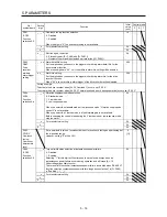
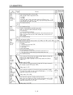
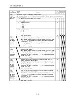
PB24
*MVS
Slight
vibration
suppression
control
_ _ _ x Slight vibration suppression control selection
Select the slight vibration suppression control.
0: Disabled
1: Enabled
To enable the slight vibration suppression control, select "Manual mode (_ _ _ 3)" of
"Gain adjustment mode selection" in [Pr. PA08]. Slight vibration suppression control
cannot be used in the speed control mode.
0h
_ _ x _ For manufacturer setting
0h
_ x _ _
0h
x _ _ _
0h
_ _ _ x For manufacturer setting
0h
PB25
*BOP1
Function
selection B-1
_ _ x _ Position acceleration/deceleration filter type selection
Select the position acceleration/deceleration filter type.
0: Primary delay
1: Linear acceleration/deceleration
When you select "Linear acceleration/deceleration", do not switch the control mode.
Doing so will cause the servo motor to make a sudden stop at the time of control
mode switching.
0h
_ x _ _ For manufacturer setting
0h
x _ _ _
0h
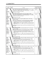
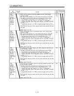
Select the gain switching condition.
Set conditions to enable the gain switching values set in [Pr. PB29] to [Pr. PB36] and [Pr. PB56] to [Pr. PB60].
PB26
*CDP
Gain
switching
function
_ _ _ x Gain switching selection
0: Disabled
1: Input device (gain switching (CDP))
2: Command frequency
3: Droop pulses
4: Servo motor speed
0h
_ _ x _ Gain switching condition selection
0: Gain after switching is enabled with gain switching condition or more
1: Gain after switching is enabled with gain switching condition or less
0h
_ x _ _ For manufacturer setting
0h
x _ _ _
0h
PB27
CDL
Gain
switching
condition
This is used to set the value of gain switching (command frequency, droop pulses,
and servo motor speed) selected in [Pr. PB26].
The set value unit differs depending on the switching condition item. (Refer to
section 7.2.3.)
Setting range: 0 to 9999
10
[kpulse/s]
/[pulse]
/[r/min]
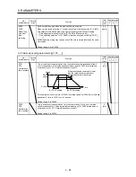
PB28
CDT
Gain
switching
time constant
This is used to set the time constant at which the gains will change in response to
the conditions set in [Pr. PB26] and [Pr. PB27].
Setting range: 0 to 100
1
[ms]
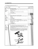
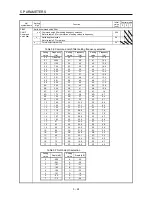
PB29
GD2B
Load to motor
inertia ratio
after gain
switching
This is used to set the load to motor inertia ratio when gain switching is enabled.
This parameter is enabled only when you select "Manual mode (_ _ _ 3)" of "Gain
adjustment mode selection" in [Pr. PA08].
Setting range: 0.00 to 300.00
7.00
[Multipli
er]
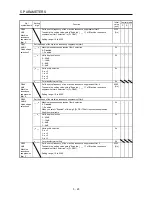
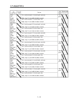
PB30
PG2B
Gain
switching
position loop
gain
Set the position loop gain when the gain switching is enabled.
When you set a value less than 1.0 rad/s, the value will be the same as [Pr. PB08].
This parameter is enabled only when you select "Manual mode (_ _ _ 3)" of "Gain
adjustment mode selection" in [Pr. PA08].
Setting range: 0.0 to 2000.0
0.0
[rad/s]
Summary of Contents for MELSERVO-JE MR-JE-100A
Page 23: ...1 FUNCTIONS AND CONFIGURATION 1 12 MEMO ...
Page 29: ...2 INSTALLATION 2 6 MEMO ...
Page 91: ...3 SIGNALS AND WIRING 3 62 MEMO ...
Page 171: ...5 PARAMETERS 5 44 MEMO ...
Page 195: ...6 NORMAL GAIN ADJUSTMENT 6 24 MEMO ...
Page 221: ...7 SPECIAL ADJUSTMENT FUNCTIONS 7 26 MEMO ...
Page 249: ...8 TROUBLESHOOTING 8 28 MEMO ...
Page 255: ...9 DIMENSIONS 9 6 MEMO ...
Page 263: ...10 CHARACTERISTICS 10 8 MEMO ...
Page 293: ...11 OPTIONS AND PERIPHERAL EQUIPMENT 11 30 MEMO ...

