5. PARAMETERS
5 - 40
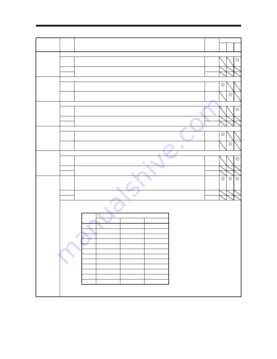
Control mode
No./
symbol/name
Setting
digit
Function
Initial
value
[unit]
P
S
T
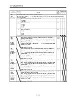
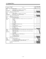
Any input device can be assigned to the CN1-41 pin.
_ _ x x Torque control mode - Device selection
Refer to table 5.9 in [Pr. PD03] for settings.
08h
PD14
*DI6H
Input device
selection 6H
_ x _ _ For manufacturer setting
0h
x _ _ _
0h
Any input device can be assigned to the CN1-43 pin.
_ _ x x Position control mode - Device selection
Refer to table 5.9 in [Pr. PD03] for settings.
0Ah
PD17
*DI8L
Input device
selection 8L
x x _ _ Speed control mode - Device selection
Refer to table 5.9 in [Pr. PD03] for settings.
0Ah
Any input device can be assigned to the CN1-43 pin.
_ _ x x Torque control mode - Device selection
Refer to table 5.9 in [Pr. PD03] for settings.
00h
PD18
*DI8H
Input device
selection 8H
_ x _ _ For manufacturer setting
0h
x _ _ _
0h
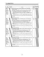
Any input device can be assigned to the CN1-44 pin.
_ _ x x Position control mode - Device selection
Refer to table 5.9 in [Pr. PD03] for settings.
0Bh
PD19
*DI9L
Input device
selection 9L
x x _ _ Speed control mode - Device selection
Refer to table 5.9 in [Pr. PD03] for settings.
0Bh
Any input device can be assigned to the CN1-44 pin.
_ _ x x Torque control mode - Device selection
Refer to table 5.9 in [Pr. PD03] for settings.
00h
PD20
*DI9H
Input device
selection 9H
_ x _ _ For manufacturer setting
0h
x _ _ _
0h
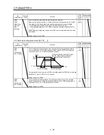
_ _ x x Device selection
Any output device can be assigned to the CN1-23 pin.
Refer to table 5.10 for settings.
0Ch
PD24
*DO2
Output device
selection 2
_ x _ _ For manufacturer setting
0h
x _ _ _
0h
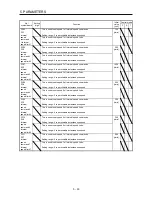
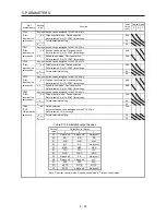
Table 5.10 Selectable output devices
Output device (Note)
Setting
value
P
S
T
00
Always off
Always off
Always off
02
RD
RD
RD
03
ALM
ALM
ALM
04
INP
SA
Always off
05
MBR
MBR
MBR
07
TLC
TLC
VLC
08
WNG
WNG
WNG
0A
Always off
SA
Always off
0B
Always off
Always off
VLC
0C
ZSP
ZSP
ZSP
0D
MTTR
MTTR
MTTR
0F
CDPS
Always off
Always off
Note. P: position control mode, S: speed control mode, T: torque control mode
Summary of Contents for MELSERVO-JE MR-JE-100A
Page 23: ...1 FUNCTIONS AND CONFIGURATION 1 12 MEMO ...
Page 29: ...2 INSTALLATION 2 6 MEMO ...
Page 91: ...3 SIGNALS AND WIRING 3 62 MEMO ...
Page 171: ...5 PARAMETERS 5 44 MEMO ...
Page 195: ...6 NORMAL GAIN ADJUSTMENT 6 24 MEMO ...
Page 221: ...7 SPECIAL ADJUSTMENT FUNCTIONS 7 26 MEMO ...
Page 249: ...8 TROUBLESHOOTING 8 28 MEMO ...
Page 255: ...9 DIMENSIONS 9 6 MEMO ...
Page 263: ...10 CHARACTERISTICS 10 8 MEMO ...
Page 293: ...11 OPTIONS AND PERIPHERAL EQUIPMENT 11 30 MEMO ...

