11. OPTIONS AND PERIPHERAL EQUIPMENT
11 - 17
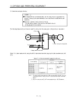
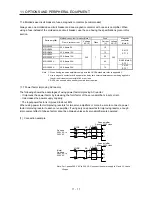
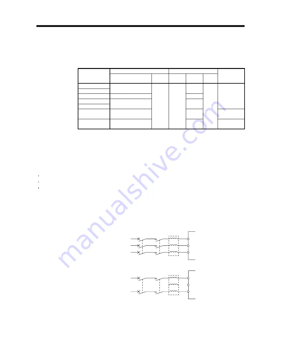
11.6 Molded-case circuit breakers, fuses, magnetic contactors (recommended)
Always use one molded-case circuit breaker and one magnetic contactor with one servo amplifier. When
using a fuse instead of the molded-case circuit breaker, use the one having the specifications given in this
section.
Molded-case circuit breaker (Note 1)
Fuse
Servo amplifier
Frame, rated current
Voltage
AC [V]
Class
Current
[A]
Voltage
AC [V]
Magnetic
contactor
(Note 2)
MR-JE-10A
MR-JE-20A
30 A frame 5 A
10
MR-JE-40A
30 A frame 10 A
15
MR-JE-70A
MR-JE-100A
30 A frame 15 A
20
S-N10
S-T10
MR-JE-200A
30 A frame 20 A
40
S-N20 (Note 3)
S-T21
MR-JE-300A
30 A frame 30 A
240
T
70
300
S-N20
S-T21
Note 1. When having the servo amplifier comply with the UL/CSA standard, refer to appendix 2.
2. Use a magnetic contactor with an operation delay time (interval between current being applied to
the coil until closure of contacts) of 80 ms or less.
3. S-N18 can be used when auxiliary contact is not required.
11.7 Power factor improving AC reactor
The following shows the advantages of using power factor improving AC reactor.
It improves the power factor by increasing the form factor of the servo amplifier's input current.
It decreases the power supply capacity.
The input power factor is improved to about 80%.
When using power factor improving reactors for two servo amplifiers or more, be sure to connect a power
factor improving reactor to each servo amplifier. If using only one power factor improving reactor, enough
improvement effect of phase factor cannot be obtained unless all servo amplifiers are operated.
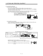
(1) Connection example
Y
Z
S
T
Y
Z
S
T
MC
MCCB
MC
MCCB
FR-HAL
Servo amplifier
3-phase 200 V class
X
R
L1
L2
L3
3-phase
200 V AC to
240 V AC
FR-HAL
Servo amplifier
1-phase 200 V class
X
R
L1
L2
(Note)
1-phase
200 V AC to
240 V AC
L3
Note. For 1-phase 200 V AC to 240 V AC, connect the power supply to L1 and L3. Leave
L2 open.
Summary of Contents for MELSERVO-JE MR-JE-100A
Page 23: ...1 FUNCTIONS AND CONFIGURATION 1 12 MEMO ...
Page 29: ...2 INSTALLATION 2 6 MEMO ...
Page 91: ...3 SIGNALS AND WIRING 3 62 MEMO ...
Page 171: ...5 PARAMETERS 5 44 MEMO ...
Page 195: ...6 NORMAL GAIN ADJUSTMENT 6 24 MEMO ...
Page 221: ...7 SPECIAL ADJUSTMENT FUNCTIONS 7 26 MEMO ...
Page 249: ...8 TROUBLESHOOTING 8 28 MEMO ...
Page 255: ...9 DIMENSIONS 9 6 MEMO ...
Page 263: ...10 CHARACTERISTICS 10 8 MEMO ...
Page 293: ...11 OPTIONS AND PERIPHERAL EQUIPMENT 11 30 MEMO ...

