6. MODBUS REGISTERS
6 - 38
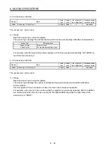
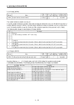
6.4.4 Control mode display (6061h)
Address Name
Data
type
Read/
write
No. of Points/
No. of Registers
Continuous read/
continuous write
6061h
Control mode display (Modes of operation Display)
1 bytes Reading
1
Impossible
The current control mode can be read.
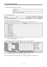
The following table shows the correspondence between control modes and setting values.
Control mode
Setting
value
Position control mode
-20
Speed control mode
-21
Torque control mode
-22
Profile position mode (pp)
1
Profile velocity mode (pv)
3
Profile torque mode (tq)
4
Homing mode (hm)
6
Test mode: JOG operation
-1
Test mode: Positioning operation
-2
Test mode: DO forced output
-4
Test mode: Machine analyzer
-6
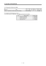
6.4.5 Software limit (607Dh)
Address Name
Data
type
Read/
write
No. of Points/
No. of Registers
Continuous read/
continuous write
607Dh
Software limit (Software
Position Limit)
Number of entries
(Number of entries)
1 bytes Reading
5 Impossible
Min Position Limit
(Stroke limit -)
4 bytes
Read/
write
Max Position Limit
(Stroke limit +)
4 bytes
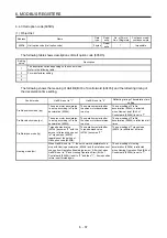
The current software limit setting can be read.
At this time, "02h" is returned to Number of entries.
The stroke limit value in the reverse direction is returned to Min Position Limit (stroke limit -) in units of
commands.
The stroke limit value in the forward direction is returned to Max Position Limit (stroke limit +) in units of
commands.
The current software limit setting can also be written.
At this time, set "02h" for Number of entries.
Set the stroke limit value in the reverse direction in Min Position Limit (stroke limit -) in units of commands.
Set the stroke limit value in the forward direction in Max Position Limit (stroke limit +) in units of commands.
If Min Position Limit (stroke limit -) and Max Position Limit (stroke limit +) are set to the same value, the
software limit function is disabled.
Summary of Contents for MELSERVO-JE MR-JE-C
Page 9: ...A 8 MEMO ...
Page 83: ...MEMO ...


