background image

10

1  SPECIFICATIONS
1.4  Servo amplifier standard specifications

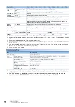
*1 This value is applicable when all I/O signals are used. Reducing the number of I/O points decreases the current capacity.
*2 If closely mounting the servo amplifiers, operate them at an ambient temperature of 0 

˚

C to 45 

˚

C or at 75 % or less of the effective load 

ratio.

*3 This current value is applicable when a 3-phase power supply is used.
*4 If using 1-phase power supply in combination with the servo motor of 750 W or higher, operate the servo amplifier at 75 % or less of the 

effective load ratio.

*5 When the servo amplifier is set to the initial setting, commands up to 1 Mpulse/s can be input. When inputting commands exceeding 1 

Mpulse/s and up to 4 Mpulses/s, change the setting in [Pr. PA13].

*6 This does not apply to connectors.

Functional safety

*1 A test pulse is a signal which instantaneously turns off a signal to the servo amplifier at a constant period for external circuits to perform 

self-diagnosis.

*2 Although the special proof tests within the mission time of the safety sub-function is not needed to be performed, the suggested 

diagnostic test interval in IEC 61800-5-2: 2016 is at least one test per three months for Category 3 PL e, SIL 3.

Torque control 
mode

Analog torque command 
input

0 V DC to ±8 V DC/maximum torque (input impedance: 10 k

Ω

 to 12 k

Ω

)

Speed limit

Set with servo parameter setting or external analog input (0 V DC to ±10 V DC/rated speed)

Fully closed loop control

Supported

Load-side 
encoder interface

MR-J5-_A

Mitsubishi Electric high-speed serial communication

MR-J5-_A-RJ

Mitsubishi Electric high-speed serial communication/A/B/Z-phase differential input signal

Protective functions

Overcurrent shut-off, regenerative overvoltage shut-off, overload shut-off (electronic thermal), servo motor 
overheat protection, encoder error protection, regenerative error protection, undervoltage protection, 
instantaneous power failure protection, overspeed protection, excessive error protection, magnetic pole 
detection protection, and linear servo control error protection

Satisfied 
standards

CE marking

LVD: EN 61800-5-1, EMC: EN 61800-3, MD: EN ISO 13849-1, EN 61800-5-2, EN 62061

UL standard

UL 61800-5-1

Structure (IP rating)

Natural cooling, open (IP20)

Force cooling, open (IP20)

Force cooling, 
open (IP20) 

*6

Close mounting 

*2

3-phase power supply input

Possible

1-phase power supply input

Possible

Impossible

Mass [kg]

0.8

1.0

1.4

2.2

3.7

6.2

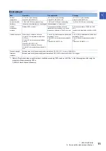
Item

Specifications

Safety sub-function

STO (IEC/EN 61800-5-2)

Safety 
performance

Satisfied standards

EN ISO 13849-1:2015 Category 3 PL e, IEC 61508 SIL 3, EN 62061 SIL CL3, EN 61800-5-2

Response performance

8 ms or less (STO input off 

 energy shut off)

Test pulse input (STO) 

*1

Test pulse interval: 1 Hz to 25 Hz, test pulse off time: Up to 1 ms

Mean time to dangerous failure 
(MTTFd)

MTTFd 

 100 [years] (314a)

Diagnostic coverage (DC)

DC = Medium, 97.6 [%]

Probability of dangerous Failure per 
Hour (PFH)

PFH = 6.4 × 10

-9

 [1/h]

Mission time (T

M

*2

T

M

 = 20 [year]

Model: MR-J5-

10A

20A

40A

60A

70A

100A

200A

350A

500A

700A

Summary of Contents for Melservo MR-J5-A

Page 1: ...MR J5 A User s Manual Introduction MR J5 _A_ Mitsubishi Electric AC Servo System ...

Page 2: ......

Page 3: ... Please follow the instructions of both levels because they are important to personnel safety Forbidden actions and required actions are indicated by the following diagrammatic symbols In this manual precautions for hazards that can lead to property damage instructions for other functions and other information are shown separately in the POINT area After reading this manual keep it accessible to t...

Page 4: ...do the work To prevent an electric shock mount the servo amplifier before wiring To prevent an electric shock connect the protective earth PE terminal of the servo amplifier to the protective earth PE of the cabinet then connect the grounding lead wire to the ground To prevent an electric shock do not touch the conductive parts WARNING To prevent an electric shock do not operate the switches with ...

Page 5: ...tor User s Manual HK series SH NA 030314ENG 4 Linear Servo Motor User s Manual LM H3 LM U2 LM F LM K2 series SH NA 030316ENG Linear Servo Motor User s Manual LM AJ series IB NA 0300518ENG 5 Direct Drive Motor User s Manual SH NA 030318ENG 6 MR J5 Partner s Encoder User s Manual SH NA 030320ENG 7 MR J5 User s Manual Function SH NA 030300ENG 8 MR J5 User s Manual Adjustment SH NA 030306ENG 9 MR J5 A...

Page 6: ...me is Function selection A 1 the setting digit name is Forced stop deceleration function selection and the setting digit is the forth last digit in PA04 the servo parameter is expressed as shown below Pr PA04 3 Forced stop deceleration function selection U S CUSTOMARY UNITS U S customary units are not shown in this manual Convert the values if necessary according to the following table Servo param...

Page 7: ...fier 26 Display sequence 26 Status display 28 Diagnostic mode 35 Alarm mode 37 Parameter mode 38 External I O signal display 40 Output signal DO forced output 41 Test operation mode 41 CHAPTER 4 STARTUP 44 4 1 Turning on servo amplifier for the first time 47 Test operation of the servo motor alone in test operation mode 48 Equipment configuration setting 49 Controller related setting 49 Operation ...

Page 8: ...ANCE WITH GLOBAL STANDARDS 67 6 1 Compliance with global standards 67 6 2 Handling of AC servo amplifier batteries for the United Nations Recommendations on the Transport of Dangerous Goods 67 6 3 Symbol for the new EU Battery Directive 69 6 4 Compliance with China Compulsory Certification CCC 70 6 5 Compliance with the China RoHS directive 71 REVISIONS 74 WARRANTY 75 TRADEMARKS 76 ...

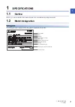
Page 9: ...analog voltage commands 1 2 Model designation Rating plate The following shows an example of the rating plate for explanation of each item Serial number Model Capacity Applicable power supply Rated output Standard manual number Ambient temperature IP rating KC certification number The year and month of manufacture Country of origin ...

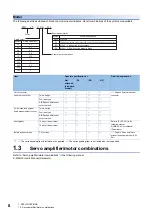
Page 10: ...pe Four wire type A B Z phase differential output method Fully closed loop system Scale measurement function Two wire type Four wire type A B Z phase differential output method Analog input 14 bits or its equivalent Refer to Pr PC60 1 in the following manual MR J5 A User s Manual Parameters 16 bits or its equivalent Built in dynamic brake 7 kW or less Page 14 Servo amplifiers without the dynamic b...

Page 11: ...rmissible frequency fluctuation Within 5 Power consumption W 30 Inrush current A Refer to Inrush currents at power on of main circuit and control circuit in the following manual MR J5 User s Manual Hardware Interface power supply Voltage 24 V DC 10 Current capacity A 0 5 including CN8 connector signals 1 Control method Sine wave PWM control current control method Dynamic brake Built in Communicati...

Page 12: ...put 0 V DC to 10 V DC rated speed Fully closed loop control Supported Load side encoder interface MR J5 _A Mitsubishi Electric high speed serial communication MR J5 _A RJ Mitsubishi Electric high speed serial communication A B Z phase differential input signal Protective functions Overcurrent shut off regenerative overvoltage shut off overload shut off electronic thermal servo motor overheat prote...

Page 13: ...ransportation conditions Must be transported by ground sea or air at an atmospheric pressure of 700 hPa or more Atmospheric pressure 700 hPa to 1060 hPa equivalent to the altitude of 400 m to 3000 m Vibration resistance When there is continuous vibration 10 Hz to 57 Hz displacement amplitude 0 075 mm 57 Hz to 150 Hz acceleration amplitude 9 8 m s2 Class 3M1 IEC 60721 3 3 When there is continuous v...

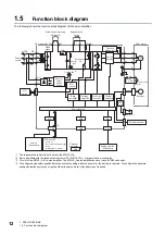
Page 14: ...ion system by using the HK series servo motor the battery is not required U U U L11 L21 N C D L3 L2 L1 MC MCCB U V W U V W P3 P4 P B RA B1 B2 CN4 M CN2 CN8 CN5 CN6 I F USB D A A D USB CN3 1 CN2L 3 E Power factor improving DC reactor Regenerative option Servo amplifier Servo motor Diode stack Dynamic brake circuit Relay Current detector Power supply Regenerative TR Charge light Cooling fan 2 Electr...

Page 15: ...ot have a CN2L connector If using the MR J5 _A RJ servo amplifier in a linear servo system or a fully closed loop system connect an external encoder to this connector Refer to the following for the compatible external encoders Page 24 Parts identification CN5 P C L11 L21 P3 P4 MR Configurator2 CN6 CN8 CN3 CN2 W V U L1 L2 L3 1 MC CN2L 2 R S T C N 4 L2 L3 N P3 P4 P C D L11 L21 U V W L1 C N 1 C N 5 C...

Page 16: ...ncy stop alarm and servo motor stop at power supply shut off When the following servo motors are being used the electronic dynamic brake may be activated at an alarm occurrence Setting the following servo parameter disables the electronic dynamic brake When Pr PA04 3 is set to 2 initial value the forced stop deceleration function may be executed at an alarm occurrence Setting Pr PA04 3 to 0 disabl...

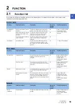
Page 17: ...ration A0 Page 57 Test operation Functions Detailed functions Description Supported firmware version Detailed explanation Universal drive Linear servo motor Using the linear servo motor and linear encoder enables the linear servo system to be configured A0 Refer to USING A LINEAR SERVO MOTOR in the following manual MR J5 User s Manual Hardware Direct drive motor Using this function enables the dir...

Page 18: ... selected from among three different types A0 Refer to Position control mode P in the following manual MR J5 User s Manual Function Rotation travel direction selection This function sets the rotation direction of the servo motor without changing the command polarity A0 Refer to Rotation travel direction selection in the following manual MR J5 User s Manual Function Electronic gear This function pe...

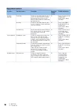
Page 19: ... s Manual Adjustment Robust filter This function improves a disturbance response when a response performance cannot be increased because of a large load to motor inertia ratio such as a roll feed axis A0 Refer to Robust filter in the following manual MR J5 User s Manual Adjustment Slight vibration suppression control This function suppresses vibration of 1 pulse generated at each servo motor stop ...

Page 20: ... User s Manual Adjustment Custom adjustment Model adaptive control This function enables control according to the ideal model that is both stable and highly responsive This is a two degrees of freedom model and can adjust responses to commands and disturbances separately This function can also be disabled A0 Refer to MODEL ADAPTIVE CONTROL in the following manual MR J5 User s Manual Adjustment Gai...

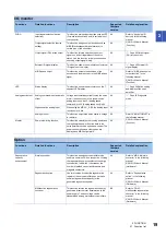
Page 21: ...ut such as VC Analog speed command or VLA Analog speed limit is 0 V A0 Page 35 Diagnostic mode High resolution analog input When using the MR J5 _A RJ the analog input resolution is 16 bits A0 Analog monitor This function outputs the servo status in voltage in real time A0 Refer to MONITORING in the following manual MR J5 User s Manual Function Monitor Power monitoring function This function calcu...

Page 22: ...cts a disconnection in the main circuit power supply input and the servo motor power supply output A0 Refer to Disconnection incorrect wiring detection function in the following manual MR J5 User s Manual Function Coasting distance reduction Forced stop deceleration function This function decelerates the servo motor to a stop at EM2 Forced stop 2 off or when there is an alarm A0 Refer to Forced st...

Page 23: ...nction This function uses the electrical energy charged in the capacitor to avoid triggering AL 010 Undervoltage in case that an instantaneous power failure occurs during operation Use a 3 phase power supply for the input power supply of the servo amplifier Using a 1 phase 200 V AC for the input power supply will not comply with SEMI F47 standard A0 Refer to Compliance with SEMI F47 standard in th...

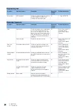
Page 24: ...ng manual MR J5 User s Manual Function Motor life diagnosis function This function predicts failures of the equipment and the servo motor based on the machine total travel distance It gives an indication of the replacement time for the servo motor A0 Machine diagnosis function This function uses the data in the servo amplifier to estimate the friction and vibrational component of the drive system ...

Page 25: ... Security To completely prevent unauthorized access to the system from external devices the user also must take safety measures Mitsubishi Electric Corporation cannot be held responsible for any problems caused by unauthorized access ...

Page 26: ...ng mode Page 26 Switch setting and display of the servo amplifier 3 USB communication connector CN5 Connect with a personal computer 4 Ethernet cable connector CN1 Connect with a personal computer 5 Analog monitor connector CN6 Outputs the analog monitor Refer to Connectors and pin assignments in the following manual MR J5 User s Manual Hardware 6 Functional safety I O signal connector CN8 Connect...

Page 27: ...N4 To use the direct drive motor connect the battery for absolute position data backup Refer to ABSOLUTE POSITION DETECTION SYSTEM in the following manual MR J5 User s Manual Hardware 11 Main circuit power connector CNP1 2 Connect the input power supply Refer to Explanation of power supply system in the following manual MR J5 User s Manual Hardware 12 Control circuit power connector CNP2 2 Connect...

Page 28: ...performing the one touch tuning Refer to One touch tuning in the following manual MR J5 User s Manual Adjustment Diagnostics The status display of each servo amplifier such as sequence display and external I O signal display and test operation are enabled Page 35 Diagnostic mode Alarm The current alarm alarm history and servo parameter error No are displayed Page 37 Alarm mode SFTY 5 digit 7 segme...

Page 29: ...vo parameters The I O setting parameters can be displayed and set Extension setting 2 servo parameters The extension setting 2 parameters can be displayed and set Extension setting 3 servo parameters The extension setting 3 parameters can be displayed and set For manufacturer setting This is for manufacturer setting For manufacturer setting This is for manufacturer setting Motor extension setting ...

Page 30: ...e status display mode by pressing MODE pressing UP or DOWN button changes the display as follows The status that can be displayed differs depending on the operation mode or control mode Refer to the following for details Page 29 Status display list Display examples Item Status Display method Servo motor speed 2500 r min in the forward rotation 3000 r min in the reverse rotation Load to motor inert...

Page 31: ... actual value because the servo amplifier display is five digits The number of pulses is displayed in the units of encoder pulses Cumulative command pulses pulse Position command input pulses are counted and displayed As the value before being multiplied by the electronic gear CMX CDV is displayed the value may not match the indicated cumulative feedback pulses The values in excess of 99999 can be...

Page 32: ...tion the value is added Position within one revolution 1000 pulses unit 1000 pulses The position within one revolution is displayed by increments of 1000 pulses unit of the encoder When the servo motor rotates in the CCW direction the value is added ABS counter rev The travel distance from the home position is displayed as multi revolution counter value of the absolution position encoder in the ab...

Page 33: ... can be counted However the counter shows only the lower five digits of the actual value because the servo amplifier display is five digits Unit total power consumption 2 increment of 100 kWh 100 kWh The unit total power consumption by increment of 100 kWh is displayed The positive value is accumulated during power running while negative value is accumulated during regeneration Cumulative feedback...

Page 34: ...de encoder 0 is displayed If an absolute position linear encoder is used as the load side encoder 0 is displayed If a rotary encoder is used as the load side encoder the multi revolution counter value of the encoder is displayed Motor side encoder information 1 1 pulse unit 3 pulse The position within one revolution of the motor side encoder is displayed in the encoder pulse unit For an incrementa...

Page 35: ... mark For absolute position linear encoder the absolute position of encoder is displayed When the count exceeds 99999 it starts from 0 This is displayed only when the linear servo motor is used Z phase counter high 100000 pulses The Z phase counter is displayed by increments of 100000 pulses of the encoder For an incremental linear encoder the Z phase counter is displayed The value is counted up f...

Page 36: ...de Displayed items Position Cumulative feedback pulses Position speed Cumulative feedback pulses servo motor speed Speed Servo motor speed Speed torque Servo motor speed analog torque command voltage Torque Analog torque command voltage Torque position Analog torque command voltage cumulative feedback pulses Display Status Description Updating Indicates that a firmware update is in progress Initia...

Page 37: ...output Allows digital output signal to be switched on off forcibly Page 41 Output signal DO forced output Test operation mode JOG operation The JOG operation can be performed without commands from an external controller Page 42 JOG operation Positioning operation The positioning operation can be performed without commands from an external controller MR Configurator2 is required to perform the posi...

Page 38: ... the analog command input 1 automatic offset is performed and 0 V is inputted the servo motor may not stop completely due to an internal error To completely stop the servo motor switch off ST1 or ST2 and stop Servo motor series ID Press the SET button to display the series ID of the servo motor currently connected For the description of each display refer to Rotary servo motor ID codes in the foll...

Page 39: ...s AL 050 1 Thermal overload error 1 during operation When an alarm is recorded to alarm history the 2 digit decimal point is lit Press SET to display the alarm No Indicates the second last alarm is AL 033 1 Main circuit voltage error When an alarm is recorded to alarm history the 2 digit decimal point is lit Press SET to display the alarm No Indicates that there is no sixteenth alarm in the past W...

Page 40: ...lecting the corresponding servo parameter mode with MODE button pressing UP or DOWN button changes the display as follows Pr PA01 Pr PA02 Pr PB01 Pr PB02 Pr PC01 Pr PC02 Pr PD01 Pr PD02 Pr PE01 Pr PE02 Pr PF01 Pr PF02 Pr Po01 Pr Po02 Pr PS01 Pr PS02 Pr PL01 Pr PL02 Pr PT01 Pr PT02 Pr PN01 Pr PN02 Pr PU01 Pr PU02 From alarm mode Basic setting servo parameters Gain filter servo parameters Extension ...

Page 41: ...g value using the UP or DOWN button Press the SET button once Press the SET button once The setting value is determined The setting value is determined Press the MODE button once The parameter number is displayed Press UP or DOWN to change the number Press the MODE button once Press the MODE button once Press the SET button once Setting of the first 4 digits Setting of the middle 4 digits Setting ...

Page 42: ...orrespond as shown below The CN3 13 pin and CN3 14 pin can be used on the MR J5 _A RJ servo amplifiers The LED segments corresponding to the pins are lit to indicate on and are extinguished to indicate off For pin signals in each control mode refer to Connectors and pin assignments in the following manual MR J5 User s Manual Hardware Press the MODE button once Press the MODE button once Press the ...

Page 43: ...p the servo motor with EM2 Forced stop 2 The test operation mode cannot be used in the absolute position detection system by DIO Pr PA03 0 Absolute position detection system selection set to 1 enabled absolute position detection system by DIO To perform the test operation select the incremental system in Pr PA03 MR Configurator2 is required to perform the positioning operation The test operation c...

Page 44: ... and stop of a servo motor can be done by the buttons Operate it as follows Status display Press MODE in the JOG operation ready status to call the status display screen When the JOG operation is performed by pressing UP or DOWN the servo status during the JOG operation is displayed Every time MODE is pressed the next status display screen appears When one cycle of the screen display is complete i...

Page 45: ...operation The status display can be checked in the display section during positioning operation Press MODE in the positioning operation ready status to call the status display screen Motor less operation Without connecting a servo motor output signals and the status display can be provided in response to the input devices as if the servo motor is actually running This operation can be used to chec...

Page 46: ...Configurator2 is the software used for purposes such as servo parameter settings graph measurement display and test operation This chapter describes the startup procedure of the servo amplifier when the servo amplifier is connected to a personal computer which has MR Configurator2 installed To learn more about using MR Configurator2 refer to Help in MR Configurator2 1 Connect the servo amplifier a...

Page 47: ...45 4 3 Selecting Parameter from the project tree opens the Parameter Setting screen 4 Select a group of servo parameters in the selection tree of the Parameter Setting window to display and configure the settings ...

Page 48: ... Selected Items Write or Axis Writing 6 Abbreviated servo parameters prefixed with and servo parameters marked with are enabled after the power is cycled or a software reset is performed Click Software Reset in MR Configurator2 to perform the software reset ...

Page 49: ... servo motor disconnected from the machine operate the servo motor at the lowest speed possible and check whether the servo motor operates correctly Page 48 Test operation of the servo motor alone in test operation mode 3 Equipment configuration setting Set each servo parameter according to the equipment configuration Page 49 Equipment configuration setting 4 Controller related setting Perform nec...

Page 50: ... test operation also includes the positioning operation and program operation Page 57 Test operation In the linear servo motor control mode the JOG operation cannot be performed Check the linear servo motor operation status by using the positioning operation or by other means Page 58 Motor driving by test operation 1 Turn off the power 2 Open the JOG Mode screen of MR Configurator2 3 To operate th...

Page 51: ...according to the connection method of the limit switch In position setting Positioning completion status can be checked with in position Set this as necessary Forced stop deceleration function Stops the servo motor at EM2 Forced stop 2 off Perform settings such as the deceleration time constant Vertical axis freefall prevention function For vertical axes this function pulls up the shaft slightly W...

Page 52: ...Cumulative feedback pulses is displayed Operation by command 1 Turn on EM2 Forced stop 2 and SON Servo on When the servo amplifier is in servo on status RD Ready turns on 2 Turn on LSP Forward rotation stroke end and LSN Reverse rotation stroke end 3 When a pulse train is inputted from the controller the servo motor starts operating Give a low speed command at first to check the servo motor operat...

Page 53: ...top 2 and SON Servo on When the servo amplifier is in servo on status RD Ready turns on 2 Turn on LSP Forward rotation stroke end and LSN Reverse rotation stroke end 3 When VC Analog speed command is inputted from the controller and ST1 Forward rotation start or ST2 Reverse rotation start is turned on the servo motor starts operating Give a low speed command at first to check the servo motor opera...

Page 54: ...splayed Operation by command 1 Turn on SON Servo on When the servo amplifier is in servo on status RD Ready turns on 2 When TC Analog speed command is inputted from the controller and RS1 Forward rotation start or RS2 Reverse rotation start is turned on the servo motor starts operating Give a low torque command at first to check the servo motor operations such as the rotation direction If the serv...

Page 55: ...er command confirm that the servo motor can be operated properly in accordance with the following procedure 1 Display the Display All window in MR Configurator2 Confirm that there is no error in the items such as servo motor speed and load ratio 2 Display the I O Monitor window Confirm that there is no error in the I O signal ...

Page 56: ...the dynamic brake Refer to the following for the details of alarms MR J5 User s Manual Troubleshooting EM2 Forced stop 2 off The servo motor decelerates to a stop AL 0E6 Servo forced stop warning occurs In the torque mode EM2 functions the same as EM1 STO STO1 and STO2 off The base circuit is shut off and the dynamic brake operates to stop the servo motor Limit switch off When LSP Forward rotation...

Page 57: ...limit level is too low against the load torque 5 Operation of the servo motor alone by command Torque control mode The servo motor does not operate Check the input voltage of TC Analog torque command on the status display The analog torque command is 0 V Refer to Torque control mode T in the following manual MR J5 User s Manual Function Check the on off status of input signal with the external I O...

Page 58: ...en collector type to the differential line driver type Wire separately from the strong electric circuit Install a data line filter MR J5 User s Manual Hardware Change the setting of Pr PA13 Command pulse input form During operation SON Servo on LSP Forward rotation stroke end or LSN Reverse rotation stroke end was switched off or CR Clear or RES Reset was switched on Cause C When C Δℓ M Mechanical...

Page 59: ...d MR Configurator2 operations such as the JOG operation positioning operation output signal forced output and program operation can be performed Precautions The test operation mode is designed for checking servo operation This mode is not for checking machine operation Do not use this mode with the machine Use this mode only with the servo motor Execution method Test operation mode is enabled by M...

Page 60: ...eration When changing the speed to the permissible speed set the speed in Pr PA28 4 Speed range limit selection Limit switch automatic ON 2 JOG operation can be performed when the limit switch is not connected Be sure to avoid causing a collision while performing the operation Operation 3 The servo motor can be started CCW CW paused stopped or forcibly stopped Clicking Start starts the operation W...

Page 61: ... to avoid causing a collision while performing the operation Move until Z phase signal 3 When Z phase signal movement is selected the servo motor moves until the first Z phase signal after positioning operation Operation 4 The servo motor can be started CCW CW paused stopped or forcibly stopped Clicking Operation Start starts the operation in the specified operation condition Repeat operation 5 Se...

Page 62: ...m Edit in the program operation screen opens the Program Edit screen Input the program and click OK For program commands refer to Help of MR Configurator2 No Item Screen operation 1 Program display Displays the program To edit the display item click Program Edit 2 Operation The servo motor can be started CCW CW paused stopped or forcibly stopped Clicking Operation Start starts the operation 3 Repe...

Page 63: ... operation selection to 1 enabled To terminate the motor less operation set Pr PC60 0 to 0 disabled Load conditions The operation is performed in the following conditions Note that the conditions may differ from those of actual machines Alarm In the motor less operation some alarms and warnings are not generated The following are examples of alarms which do not occur AL 016 Encoder initial communi...

Page 64: ...he servo status Use this function for purposes such as checking output signal wiring Operate this function on the DO Forced Output screen of MR Configurator2 Each output signal can be turned on off by clicking the ON OFF button next to its name After checking click Test Operation Mode Cancel and terminate the output signal DO forced output ...

Page 65: ...isconnected from the network and directly connected to MR Mode Change via a USB cable Initialization procedure by MR Mode Change Open MR Mode Change and use a USB cable to connect the servo amplifier that will be initialized with a personal computer Turn on the servo amplifier control circuit power supply Confirm that Reset to factory settings is selected then click Write After the writing is comp...

Page 66: ... for loose terminal block screws Retighten any loose screws Check the cables and the like for scratches or cracks Inspect them periodically according to operating conditions especially when the servo motor is movable Check that the connector is securely connected to the servo amplifier Check that the wires are not coming out from the connector Check for dust accumulation on the servo amplifier Che...

Page 67: ...s A relay will reach the end of its service life if the following actions are performed a total of 100 000 times powering on the servo amplifier inputting the EM1 command Forced stop 1 and inputting the quick stop command from the servo controller In addition the service life of a relay may vary depending on the power supply capacity Servo amplifier cooling fan The cooling fan bearings will reach ...

Page 68: ...not directly touch conductive areas such as the connector pins and electrical parts The fan unit is composed of a cooling fan and its cover List of applicable fan units Replacement procedure For the replacement procedure of fan units refer to Fan unit replacement procedure in the following manual MR J5 User s Manual Hardware Servo amplifier Fan units MR J5 70A_ MR J5 100A_ MR J5 FAN1 MR J5 200A_ M...

Page 69: ... lithium metal batteries Change in regulations The following points have been changed for lithium metal batteries transportation by sea or air based on the IATA Dangerous Goods Regulations 54th edition effective January 1 2013 in addition to the revision of the Recommendations of the United Nations Rev 15 and the ICAO TI 2009 2010 Edition For lithium metal batteries battery cells alone are classif...

Page 70: ...he Shipper s Declaration for Dangerous Goods are required for transportation Please attach the documentation to the packages and the outer package of the overpack The requirements of the IATA Dangerous Goods Regulations are subject to change according to the annual revision When customers transport lithium batteries by themselves the responsibility for the cargo lies with the customers Thus be sur...

Page 71: ...aterials and components which can be recycled and or reused This symbol means that batteries and accumulators at their end of life should be disposed of separately from household waste If a chemical symbol is shown beneath the above symbol a heavy metal of the corresponding chemical symbol is contained in the battery or the accumulator with the following standard concentration or more This will be...

Page 72: ...compliance with the relevant technical standards or products declared by the manufacturer as being compliant must carry the specified mark CCC mark Many of the technical standards to be applied are GB standards Chinese national standards which comply with global standards such as those set forth by the IEC International Electrotechnical Commission and CISPR International Special Committee on Radio...

Page 73: ... substance contained in all of the homogeneous materials for this part is below the limit requirement of GB T26572 Indicates that said hazardous substance contained in at least one of the homogeneous materials for this part is above the limit requirement of GB T26572 2 Indications based on Marking for the restriction of the use of hazardous substances in electrical and electronic products SJ T1136...

Page 74: ...ht or more lead Electrical and electronic components such as piezoelectric sensors containing lead in glass or ceramic materials but not including the dielectric ceramics used in capacitors Electrical and electronic components containing lead in a glass or ceramic matrix compound e g chip resistors Status of our products for compliance with the China RoHS directive Chinese The following table is g...

Page 75: ...6 COMPLIANCE WITH GLOBAL STANDARDS 6 5 Compliance with the China RoHS directive 73 6 MEMO ...

Page 76: ... SH NA 030296ENG C MR J5 500A_ MR J5 700G_ and models without the dynamic brake are added The following functions are added Multifunction regeneration converter Added sections Section 1 3 Section 1 7 Section 6 4 This manual confers no industrial property rights or any rights of any other kind nor does it confer any patent licenses Mitsubishi Electric Corporation cannot be held responsible for any ...

Page 77: ...u acknowledge we are not responsible for 2 Term of warranty after the stop of production 1 We may accept the repair at charge for another seven 7 years after the production of the product is discontinued The announcement of the stop of production for each model can be seen in our Sales and Service etc 2 Please note that the Product including its spare parts cannot be ordered after its stop of prod...

Page 78: ...trademark or registered trademark of Mitsubishi Electric Corporation in Japan and or other countries All other product names and company names are trademarks or registered trademarks of their respective companies SH NA 030296ENG C ...

Page 79: ......

Page 80: ...notice When exported from Japan this manual does not require application to the Ministry of Economy Trade and Industry for service transaction permission HEAD OFFICE TOKYO BUILDING 2 7 3 MARUNOUCHI CHIYODA KU TOKYO 100 8310 JAPAN NAGOYA WORKS 1 14 YADA MINAMI 5 CHOME HIGASHI KU NAGOYA JAPAN ...

Reviews: