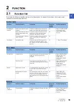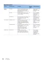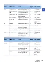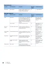
24
3 STRUCTURE
3.1 Parts identification
3
STRUCTURE
3.1
Parts identification
MR-J5-_A_
The diagram shows MR-J5-10A-RJ.
No.
Name
Application
Detailed explanation
(1)
Display section
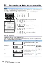
The 5-digit, 7-segment LED display shows the servo status and
alarm number.
display of the servo amplifier
(2)
Operation section
Used to perform status display, diagnostic, alarm, and servo
parameter setting operations. Push the "MODE" and "SET" at the
same time for 3 s or more to switch to the one-touch tuning mode.
display of the servo amplifier
(3)
USB communication connector (CN5)
Connect with a personal computer.
(4)
Ethernet cable connector (CN1)
Connect with a personal computer.
(5)
Analog monitor connector (CN6)
Outputs the analog monitor.
Refer to "Connectors and pin
assignments" in the following
manual.
MR-J5 User's Manual
(Hardware)
(6)
Functional safety I/O signal connector
(CN8)
Connect an external safety relay to use the STO function.
Refer to "USING STO
FUNCTION" in the following
manual.
MR-J5 User's Manual
(Hardware)
SFTY
C
N
4
L2
L3
N-
P3
P4
P+
C
D
L11
L21
U
V
W
L1
C
N
1
C
N
5
C
N
6
C
N
8
C
N
2
C
N
3
C
N
2
L
(1)
(3)
(4)
(2)
(5)
(6)
(7)
(8)
(9)
(10)
(11)
(12)
(13)
(15)
(14)
(16)
(17)
Bottom
Side
Inside of the display cover

