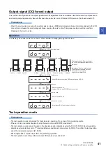
26
3 STRUCTURE
3.2 Switch setting and display of the servo amplifier
3.2
Switch setting and display of the servo amplifier
Outline
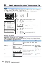
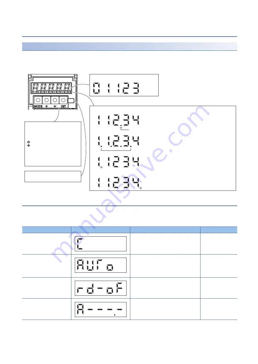
The MR-J5-_A_ servo amplifier has the display section (5-digit, 7-segment LED) and operation section (4 push buttons) for
servo amplifier status display, alarm display, servo parameter setting, etc.
Push the "MODE" and "SET" buttons at the same time for 3 s or longer to switch to the one-touch tuning mode.
Display sequence
Press the "MODE" button once to shift to the next display mode.
Use the basic setting parameters [Pr. PA19 Parameter writing prohibited] to refer to and operate the gain/filter parameters,
extension setting parameters, and I/O setting parameters.
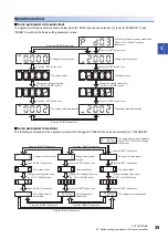
Display mode transition
Initial screen
Functions
Reference
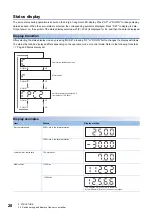
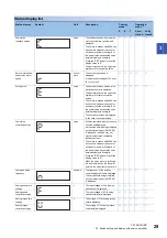
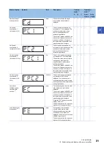
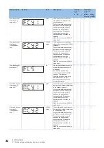
Status display
The servo status is displayed. The display at
power-on differs depending on each operation
mode.
One-touch tuning
Select this when performing the one-touch tuning.
Refer to "One-touch
tuning" in the following
manual.
MR-J5 User's
Manual (Adjustment)
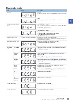
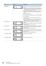
Diagnostics
The status display of each servo amplifier such as
sequence display and external I/O signal display
and test operation are enabled.
Alarm
The current alarm, alarm history, and servo
parameter error No. are displayed.
SFTY
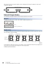
5-digit, 7-segment LED Displays the data.
Decimal LED Displays the decimal points, alarm presence/absence, and others.
Lit to indicate the decimal point.
Changes display mode
Switches Low/High
To switch to the one-touch tuning mode,
this button is pushed together with the
"SET" button for 3 s or more.
Scrolls display/data (UP)
Scrolls display/data (DOWN)
Determines display/data
Clears data
To switch to the one-touch tuning mode,
this button is pushed together with the
"MODE" button for 3 s or more.
Decimal
Lit to indicate a negative when "-" (negative) cannot
be displayed.
Blinks to indicate alarm occurrence.
Light off: Functional safety unavailable
Light on: Functional safety available
Blinks to indicate the test operation mode.
MODE
SET
SFTY

