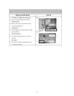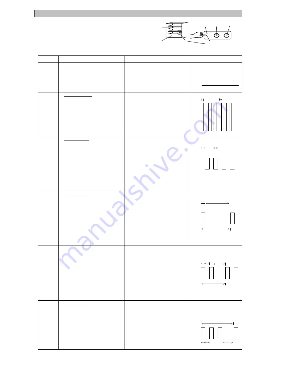
(3) LED trouble display and the check point
(3.1) LED trouble display : follow the procedure of "self check method
and its operation" at page 11. Trouble is indicated by the blinking number
of ice making stop LED.
∗
When several troubles occur, smaller blinking number of LEDs has to be indicated first.
(3.2) Check point and treatment
Normal
1. Normally display and the Auto ice-maker
system display.
* If non-power supply, it'll show as same
the effect.
Auto ice maker NG
1. The connector lead wire of Auto ice maker 1. Check all points of the Auto ice maker
is not orderly.
connector lead wire. May be un-lock
and struck insert.
2.
2.
3.
3. PCB plate ( Ref Con assy) NG
Thermistor(I) NG
1.
The connector thermistor (I) lead wire
1.
Check all points of the thermistor (I)
isn't orderly.
connector lead wire, may be unlock
and struck insert.
2.
Thermistor (I) NG (break or short)
2.
If the resistance of thermistor (I) is NG,
should be changed the thermistor and
re-check the resistance.
3.
PCB plate (Ref Con assay) NG
3.
If the resistance is OK,should be changed
PCB plate (Ref Con assy and re-check
the resistance).
Thermistor (F) NG
1. The connector thermistor (F) lead wire
1.
Check all points of the thermistor (F)
isn't orderly.
connector lead wire, may be unlock
and struck insert.
2. Thermistor (F) NG (break or short)
2.
If the resistance of thermistor (F) is
NG,should be changed the thermistor and
re-check the resistance.
3. PCB plate (Ref Con assy) NG
3.
If the resistance is OK,should be changed
PCB plate (Ref Con assy and re-check
the resistance.
Thermistor (DEF) NG
1. The connector DEF. thermistor lead wire
1.
Check all points of the thermistor
isn't orderly.
(DEF) connector lead wires, may be
unlock and struck insert.
2. Thermistor (DEF) NG (break or short)
2.
If the resistance of thermistor (DEF) is
NG,should be changed the thermistor and
re-check the resistance.
3. PCB plate (Ref Con assy) NG
3.
If the resistance is OK,should be changed
PCB plate (Ref Con assy and re-check
the resistance.
Defrost heater NG
1.
1.
2. Defrost heater break or
2.
Thermal fuse break.
and thermal fuse.
3. PCB plate (Ref Con assy) break.
3.
If the resistance is OK,should be changed
PCB plate (Ref Con assy and re-check
the resistance.
isn't orderly.
maker.
Replace and re-check the PCB plate
and non-display)
connector lead wire, may be un-lock
Blink
Blink
Light
Light
Light
1 Blink
No Light
Display function of LED
Off
NO
Function
Explanation
Light
No Light
Detecting method and corrective NG points
2 Blinks
Check the resistance of the defrost heater
and struck insert.
3 Blinks
Light
No Light
No Light
No Light
0.1 second
0.3 seconds
No Light
Replace and re-check the Auto ice
( Ref Con assy)
Auto ice maker (Motor's not rotate
The Defrost heater connector lead wire
Check all points of the defrost heater
Light
0.1 sec
5 sec
1
1
5 sec
1
2
1
2
5 sec
1
2
1
3
1 Cycle
0.1 sec
0.3 sec
0.3 sec
0.3 sec
1 Cycle
0.3 sec
1 Cycle
0.3 sec
Slide room
Refrigerator room
Ice making
stop LED
Refrigerator Freezer
Ice maker off
16
Summary of Contents for MR-C375C-OB-A
Page 2: ......
Page 9: ... SKELETON WIRING DIAGRAM MR C375C A MR C375CL A MR C405C A MR C405CL A 3 WIRING DIAGRAM 7 ...
Page 12: ...MR C375C A MR C375CL A MR C405C A MR C405CL A 5 NAMES OF PARTS 10 ...
Page 26: ...DOOR BODY PARTS MR C375C A MR C375CL A MR C405C A MR C405CL A 8 PARTS LIST 24 ...
Page 28: ...BODY PARTS MR C375C A MR C375CL A MR C405C A MR C405CL A 26 ...
Page 30: ...ELECTRICIAL PARTS MR C375C A MR C375CL A MR C405C A MR C405CL A 28 ...
Page 32: ...ACCESSORY AND UNIT PARTS MR C375C A MR C375CL A MR C405C A MR C405CL A 30 ...


