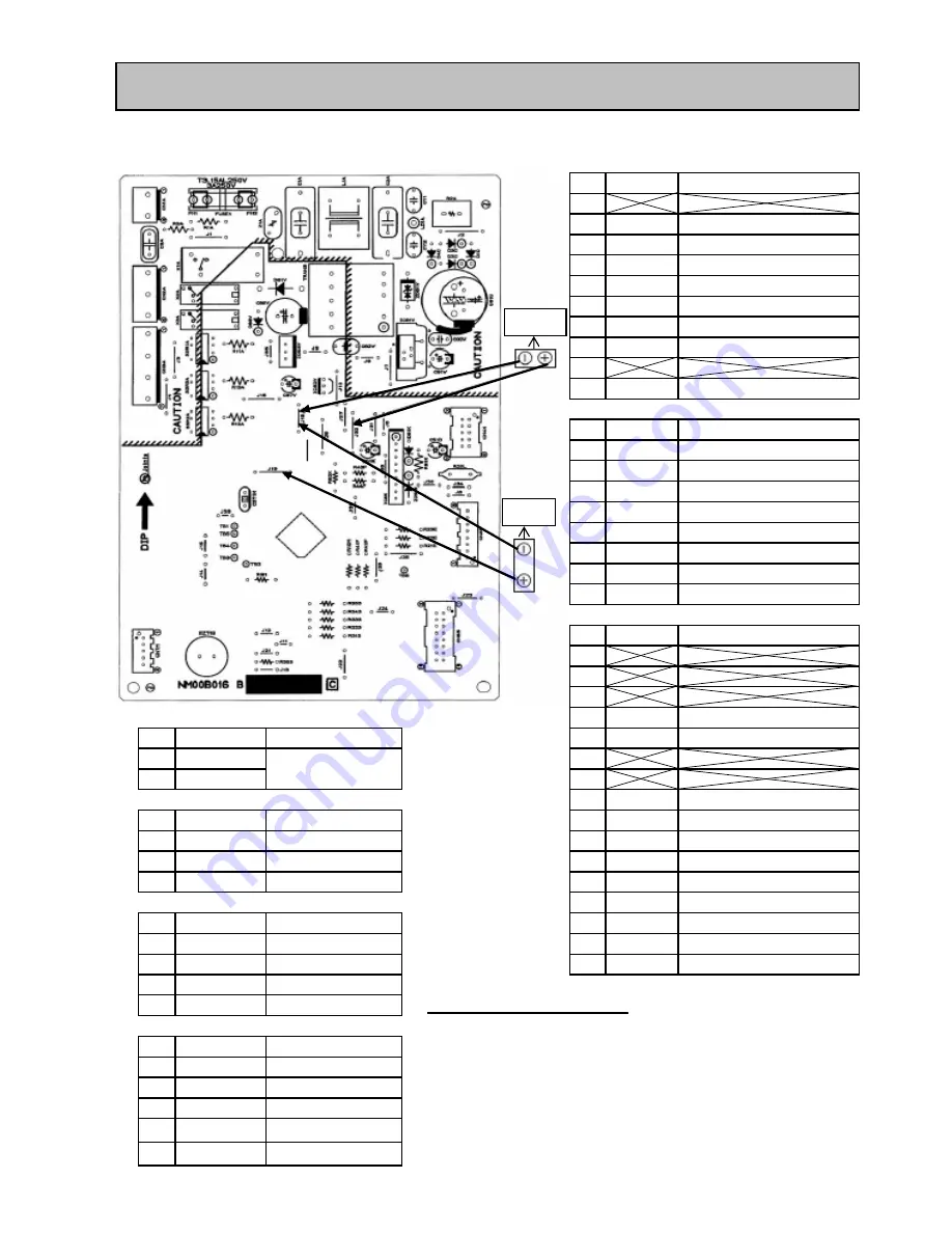
6.4 TEST POINT DIAGRAM OF MAIN CONTROL BOARD
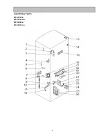
MR-C375C-A
MR-C375CL-A
MR-C405C-A
MR-C405CL-A
CN4K
1
2
Red
Damper
3
Gray
Ice Maker Positon SW
4
Bright Yellow Damper
5
Pink
Ice Maker & Water Pump Forward
6
White
Damper
7
Brown
Ice Maker Reverse
8
Blue
Damper
9
10 Yellow/Green Water Pump
CN5F
8
Violet
12 VDC Common
7
Violet
12 VDC Common
6
Black
GND
5
Pink
GND
4
Orange
Outer Fan Motor FG
3
Bright Yellow Inner Fan Motor FG
2
Light Green Outer Fan Motor Vs
1
White
Inner Fan Motor Vs
CN6S
1
2
3
4
Yellow
Ice Maker Stop SW
CN1A
5
Red
Ice Maker Stop LED
1
Grey
6
3
Black
7
8
Blue
F Thermistor
CN2A
9
Bright Yellow Temp Control Board
1
Grey
220 VAC Common
10 Orange
R Thermistor
3
White
Compressor
11 Gray
Temp Control Board
5
Red
Defrost Heater
12 Light Green I Thermistor
13 Sky Blue
5 VDC Common
CN3A
14 Pink
DEF Thermistor
1
Yellow
Lamp
15 Black
GND
3
Yellow/Green
V Heater
16 Brown
Door SW
5
Brown
Ice Maker Heater
7
Sky Blue
Pipe Heater
Compulsory defrosting method
have 2 methods as below
1) Short circuit at 2-pin connector between no.6 (white wire) with no.7 (red wire)
CN7M
at Buzzer & Thermistor A.T. board.(Inside hinge cover)
1
White
12 VDC Common
2) Open door R and then adjust dial freezer at MID position. Use magnet touch
2
Red
Buzzer
door switch in order to simulate as door closing. (lamp must no light),then turn
3
Violet
A.T. Thermistor
the dial continuously as follow COLDER
→
LOW
→
MID
4
Sky Blue
5 VDC Common
5
Grey
Compulsion DEF
Parts Name
Lead color
Lead color
Parts Name
Lead color
Parts Name
Parts Name
Lead color
Parts Name
Lead color
Parts Name
Parts Name
Lead color
Lead color
220 VAC
12 VDC
5 VDC
18
Summary of Contents for MR-C375C-OB-A
Page 2: ......
Page 9: ... SKELETON WIRING DIAGRAM MR C375C A MR C375CL A MR C405C A MR C405CL A 3 WIRING DIAGRAM 7 ...
Page 12: ...MR C375C A MR C375CL A MR C405C A MR C405CL A 5 NAMES OF PARTS 10 ...
Page 26: ...DOOR BODY PARTS MR C375C A MR C375CL A MR C405C A MR C405CL A 8 PARTS LIST 24 ...
Page 28: ...BODY PARTS MR C375C A MR C375CL A MR C405C A MR C405CL A 26 ...
Page 30: ...ELECTRICIAL PARTS MR C375C A MR C375CL A MR C405C A MR C405CL A 28 ...
Page 32: ...ACCESSORY AND UNIT PARTS MR C375C A MR C375CL A MR C405C A MR C405CL A 30 ...


