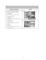
Compressor cover
(1) Remove 7 screws for compressor cover at the back of the refrigerator.
Fan motor of compressor compartment
(2) Detach the Elect cover
(3) Detach the Connector.
(4) Remove a screw that fixed bell mouth. Pull out the whole fan motor and disconnect the terminals.
(5) Pull out the fan from the fan motor.
(6) Detach the lid-fixing screw to take out the fan motor.
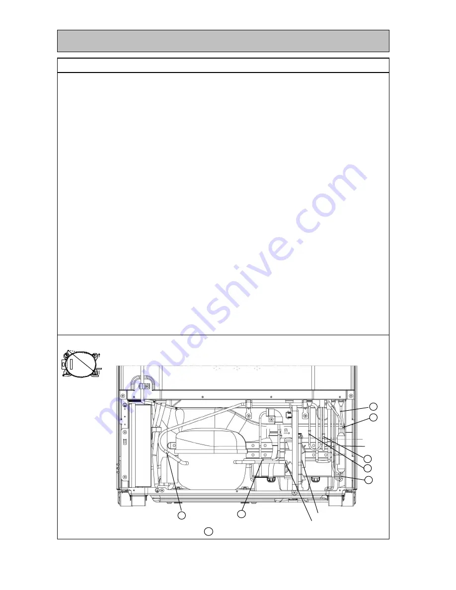
7 Detachment compressor.
(1) Collect gas from the charge pipe on the high pressure side.
(2) After collecting gas, cut the charge pipe on the low pressure side.
(3) Detach the welded section of the discharge pipe and suction pipe.
(4) Replace the compressor and the dryer at a time.
Caution on assembly
(1) After attaching the compressor, must to Vacuum and charge gas from charge pipe.
(2) Arrage the piping so that the pipe will not hit each other and compressor cover, (which causes loud noise). Then
attach the compressor cover.
(3) After all the work is complete, be sure to check the cooling preformance and the gas leak from the welded points.
OPERATING PROCEDURE
W
Attach U washer as the figure shown below
: This mark shown welded point
Fan motor (Machine room)
W
W
W
Dryer
W
W
W
W
Charge pipe(Low pressure side)
23
Summary of Contents for MR-C375C-OB-A
Page 2: ......
Page 9: ... SKELETON WIRING DIAGRAM MR C375C A MR C375CL A MR C405C A MR C405CL A 3 WIRING DIAGRAM 7 ...
Page 12: ...MR C375C A MR C375CL A MR C405C A MR C405CL A 5 NAMES OF PARTS 10 ...
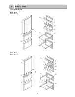
Page 26: ...DOOR BODY PARTS MR C375C A MR C375CL A MR C405C A MR C405CL A 8 PARTS LIST 24 ...
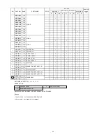
Page 28: ...BODY PARTS MR C375C A MR C375CL A MR C405C A MR C405CL A 26 ...
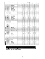
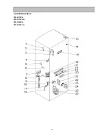
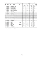
Page 30: ...ELECTRICIAL PARTS MR C375C A MR C375CL A MR C405C A MR C405CL A 28 ...
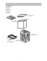
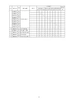
Page 32: ...ACCESSORY AND UNIT PARTS MR C375C A MR C375CL A MR C405C A MR C405CL A 30 ...


