4 STRUCTURE (PARTS IDENTIFICATION)
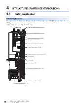
4.1 Parts identification
19
4
No.
Name
Application
Detailed explanation
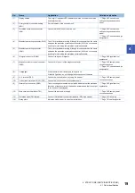
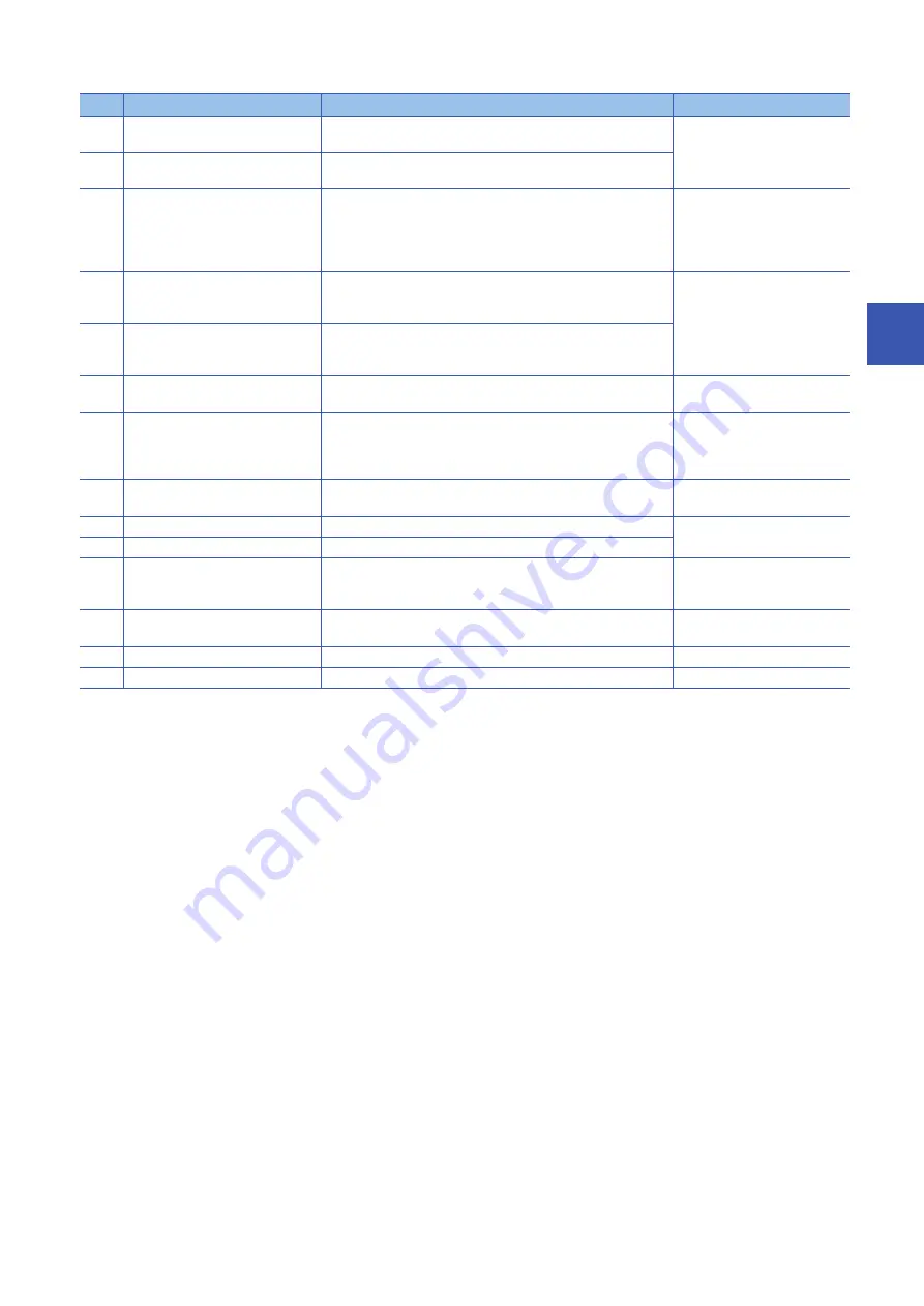
(1)
Display section
The 1-digit, 7-segment LED indicator shows the converter unit status
and alarm number.
switch settings and operation
panel
(2)
Rotary switch for converter setting
(SW1)
Set the function of the converter unit.
(3)
Protection coordination connector
(CN4)
Connect it with CN40A of the drive unit.
switch settings and operation
panel
(4)
Manufacturer setting connector (CN9)
This is for manufacturer setting. Although this connector has the same
shape as the protection coordination connector (CN4), do not connect
anything to it, including the protection coordination cable.
(5)
Manufacturer setting connector
(CN41)
This is for manufacturer setting. Although this connector has the same
shape as the protection coordination connector (CN4), do not connect
anything to it, including the protection coordination cable.
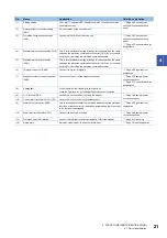
(6)
I/O signal connector (CN24)
Connect the digital I/O signals.
(7)
Magnetic contactor control connector
(CN23)
Connect it to the coil of the magnetic contactor.
(8)
Charge light
When the main circuit is charged, this light is on.
While the light is on, do not change the connections of the wires.
(9)
L+/L- terminal (TE2)
Connect it with the drive unit by using the bus bar.
(10)
Control circuit terminal L11/L21 (TE3)
Connect it with the control circuit power supply.
(11)
Alarm output connector (CN25)
This is a changeover contact output which indicates that the protective
functions of the converter unit have been activated and that the output
to the drive unit has stopped.
(12)
Main circuit terminal block (TE1)
Connect the input power supply.
(13)
Protective earth (PE) terminal
Connect this terminal to the protective earth (PE) of the cabinet.
(14)
Rating plate
Indicates model, capacity, and other information.

