28
4 STRUCTURE (PARTS IDENTIFICATION)
4.3 Converter unit switch settings and operation panel
4.3
Converter unit switch settings and operation panel
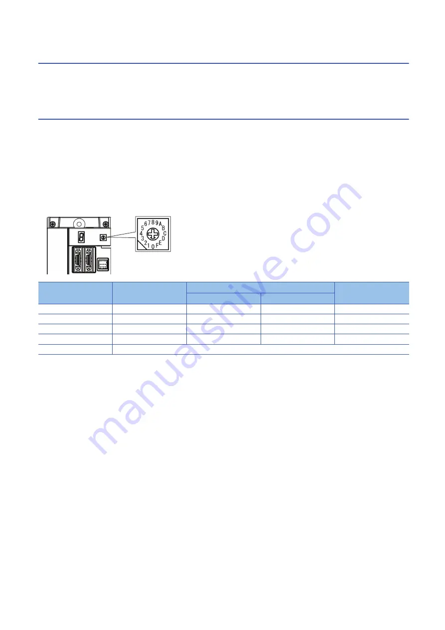
Forced stop, protection coordination, and magnetic contactor drive output can be configured by setting the converter unit
switch.
The converter unit status and alarm number can be displayed on the converter unit display (1-digit, 7-segment LED).
Switches
If a metal screw driver contacts with the conductive areas, the switches may malfunction. Therefore, use an insulated screw
driver instead of a metal screw driver to operate the rotary switch (SW1).
Do not set a value other than the listed setting values on the rotary switch for converter setting (SW1).
The setting of each switch becomes effective by cycling the main circuit power supply and the control circuit power supply.
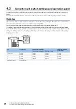
To enable/disable forced stop, protection coordination, and magnetic contactor drive output, set the rotary switch for converter
setting. The following table shows the settings of the rotary switch for converter setting and the combinations for enabling/
disabling each function.
No.
Forced stop
Protection coordination
Magnetic contactor
drive output
Protection coordination
Standalone drive
0 (initial value)
Disabled
Enabled
Disabled
Enabled
1
Disabled
Enabled
Disabled
Disabled
4
Enabled
Enabled
Disabled
Enabled
8
Disabled
Disabled
Enabled
Disabled
Other than the above
Do not use them.
Rotary switch for
setting converter (SW1)
Converter unit

