5 SIGNALS AND WIRING
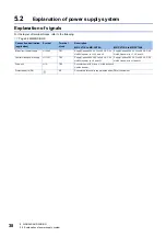
5.2 Explanation of power supply system
41
5
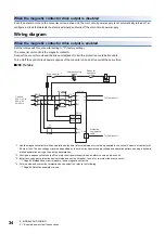
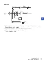
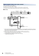
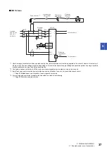
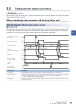
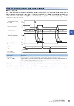
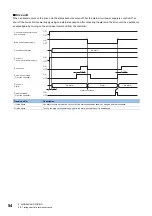
• When the magnetic contactor drive output is disabled
When an alarm occurs, turn off the magnetic contactor using an external sequence and shut off the main circuit power supply.
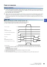
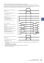
*1 If an electromagnetic brake is installed externally, configure the circuit so that the electromagnetic brake operates with MBR as
described below.
ON: Electromagnetic brake is not activated
OFF: Electromagnetic brake is activated
*2 Give a position command after the externally-installed electromagnetic brake is released.
*3 When in the position control mode.
*4 In the drive unit parameters, set the delay time (Tb) from when the MBR shuts off at servo-off until base circuit shut-off.
*5 This is the case when in the ready-on status during servo-off. In the ready-off status, the base circuit is turned off at the same time as the
servo-on command is turned off. (Tb = 0)
(95 ms)
(3 s)
*2
OFF
ON
OFF
ON
OFF
ON
OFF
ON
OFF
ON
ON
OFF
0 r/min
0 r/min
Tb
*4*5
Main circuit power supply
Base circuit
Drive unit
control circuit power supply
MBR
(Electromagnetic brake interlock)
*1
Position command
*3
Servo motor speed
Servo-on command (From the controller)
Converter unit control circuit power supply

