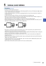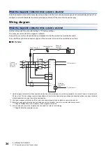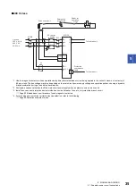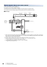
5 SIGNALS AND WIRING
5.3 Connectors and pin assignments
45
5
5.3
Connectors and pin assignments
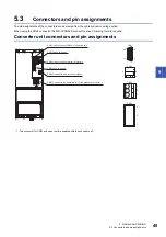
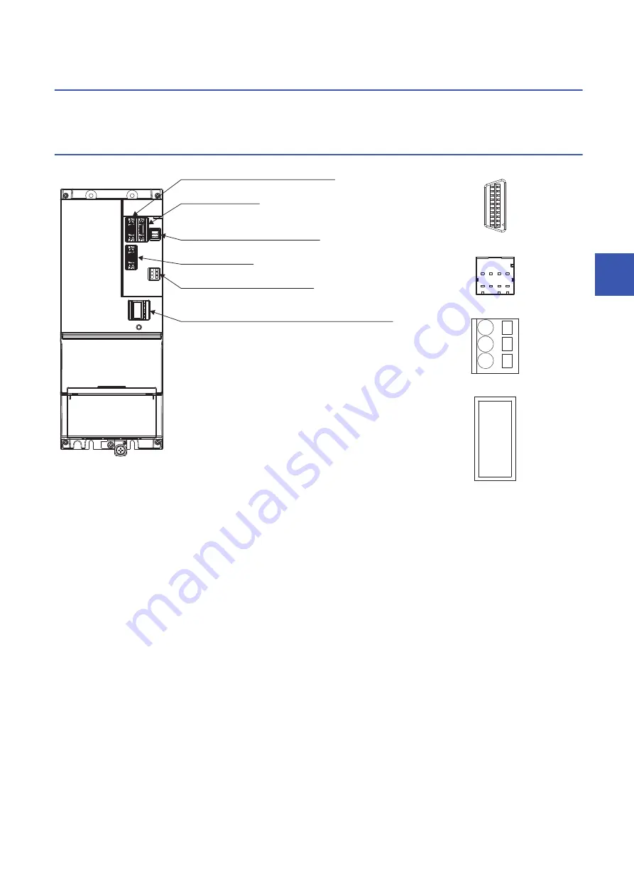
The pin assignments of the connectors are as viewed from the cable connector wiring section.
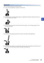
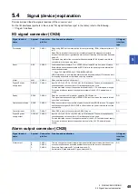
When using the CN24 connector, the MR-CVCN24S connector set and crimping tool are required.
Converter unit connectors and pin assignments
*1 The connector for CN23 and open tool are supplied with the converter unit.
CN4
CN24
CN25
A
B
8
4
5
1
20
11
10
1
C
3
2
1
CN23
CN41 Leave this open.
CN9 Leave this open.
CN25 Connect to an error output signal.
CN4 Used to connect CN40A of the drive unit.
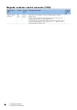
CN23 Connect to the operation coil of the magnetic contactor.
*1
CN24 Used to connect digital I/O signals.

