5 SIGNALS AND WIRING
5.5 Timing chart at alarm occurrence
51
5
5.5
Timing chart at alarm occurrence
Precautions
When an alarm occurs, remove its cause, check that the operation signal is not being inputted, ensure safety, and reset the
alarm before restarting the operation.
When combining one converter unit and one drive unit
When the magnetic contactor drive output is enabled
■
Converter unit
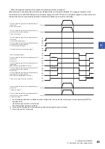
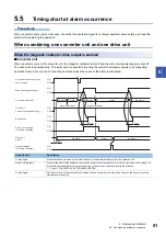
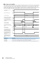
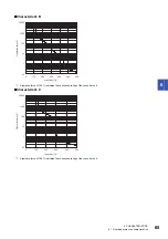
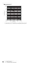
When an alarm occurs on the converter unit, the magnetic contactor turns off and the main circuit power supply is shut off.
The drive units in operation stop. The alarm can be canceled by cycling the control circuit power supply or by requesting
operation from a drive unit, but it cannot be canceled unless the cause of the alarm is eliminated.
Transition No.
Description
1) in the figure
When the drive unit is servo-off, the drive unit does not detect alarms that occur on the converter unit.
2) and 3) in the figure
To cancel the alarm of the converter unit, cycle the power of the converter unit ( 2)) or turn on the servo-on command ( 3)).
For details on which alarms can be reset by turning on the servo-on command, refer to the following.
Page 75 CONVERTER UNIT TROUBLESHOOTING
4) in the figure
If an alarm occurs on the converter unit while the drive unit is servo-on, an alarm also occurs on the drive unit, and the
status becomes servo-off.
2)
ON
OFF
ON
OFF
ON
OFF
ON
OFF
ON
OFF
(3 s)
1)
ON
OFF
1.5 s
(3 s)
4)
3)
Drive unit
Control circuit power supply
Main circuit power supply
Servo-on command
(From the controller)
Drive unit
Alarm
Base circuit
Reset command
(From the controller)
No alarm
Alarm
No alarm
No alarm
No alarm
Alarm
No alarm
Alarm occurrence
Alarm
Alarm occurrence
Converter unit control circuit
power supply
Converter unit alarm

