6 CHARACTERISTICS
6.2 Power supply capacity and generated loss
67
6
6.2
Power supply capacity and generated loss
Amount of heat generated by converter unit
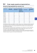
The following table indicates the generated loss and the power supply capacity of the converter unit under rated load.
Even if multiple drive units and servo amplifiers are connected to one converter unit, calculate the power supply capacity from
the capacity of the converter unit. If the total value of the output wattage of the servo motors driven by the drive units and
servo amplifiers connected to the converter unit is smaller than the converter capacity, the power supply capacity will be
smaller than the values in the table.
Because 2 to 2.5 times the instantaneous power is required during servo motor acceleration, use a power supply that can
secure a voltage within the permissible voltage fluctuation of the main circuit power supply terminals (L1/L2/L3) of the
converter unit. The power supply capacity will vary according to the power impedance.
The actual amount of generated heat depends on the frequency of use during operation and will be within the range of "At
rated output" and "At servo-off". For the design of an enclosed type cabinet, use the values in the tables in consideration for
the harshest conditions with regard to the environment and operation pattern.
Converter unit
Power supply
capacity [kVA]
Converter unit generated heat [W]
Area required for
heat dissipation
[m
2
]
At rated output
At rated output
(internal heat
generation when
cooling externally)
At servo-off
MR-CV11K
16
124
25
25
2.5
MR-CV18K
27
193
32
25
3.9
MR-CV30K
43
317
45
25
6.4
MR-CV37K
53
396
53
25
8.0
MR-CV45K
64
496
104
25
10.0
MR-CV55K
78
595
164
30
12.0
MR-CV11K4
16
124
25
25
2.5
MR-CV18K4
27
193
32
25
3.9
MR-CV30K4
43
317
45
25
6.4
MR-CV37K4
53
402
53
25
8.1
MR-CV45K4
64
496
104
25
10.0
MR-CV55K4
78
596
164
30
12.0
MR-CV75K4
107
842
228
30
16.9

