background image

SH(NA)030132ENG-E(1805)MEE     Printed in Japan 

Specifications are subject to change without notice.


This Instruction Manual uses recycled paper.

MODEL

MODEL

CODE

General-Purpose AC Servo

MR-D30 INSTRUCTION MANUAL

HEAD OFFICE: TOKYO BLDG MARUNOUCHI TOKYO 100-8310

1CW817

MR-D30 INSTRUCTIONMANUAL

Functional safety unit

MODEL

MR-D30

INSTRUCTION MANUAL

E

E

Summary of Contents for MR-D30

Page 1: ... change without notice This Instruction Manual uses recycled paper MODEL MODEL CODE General Purpose AC Servo MR D30 INSTRUCTION MANUAL HEAD OFFICE TOKYO BLDG MARUNOUCHI TOKYO 100 8310 1CW817 MR D30 INSTRUCTIONMANUAL Functional safety unit MODEL MR D30 INSTRUCTION MANUAL E E ...

Page 2: ... or severe injury CAUTION Indicates that incorrect handling may cause hazardous conditions resulting in medium or slight injury to personnel or may cause physical damage Note that the CAUTION level may lead to a serious consequence according to conditions Please follow the instructions of both levels because they are important to personnel safety What must not be done and what must be done are ind...

Page 3: ...earth PE terminal marked of the servo amplifier to the protective earth PE of the cabinet To avoid an electric shock insulate the connections of the power supply terminals 2 To prevent fire note the following CAUTION Install the servo amplifier servo motor and regenerative resistor on incombustible material Installing them directly or close to combustibles will lead to smoke or a fire Always conne...

Page 4: ...l Do not get on or put heavy load on the equipment Otherwise it may cause injury The equipment must be installed in the specified direction Leave specified clearances between the servo amplifier and the cabinet walls or other equipment Do not install or operate the servo amplifier and MR D30 which have been damaged or have any parts missing Do not block the intake and exhaust areas of the servo am...

Page 5: ...id a malfunction connect the wires to the correct phase terminals U V W of the servo amplifier and servo motor Connect the servo amplifier power output U V W to the servo motor power input U V W directly Do not let a magnetic contactor etc intervene Otherwise it may cause a malfunction U Servo motor M V W U V W U M V W U V W Servo amplifier Servo motor Servo amplifier The surge absorbing diode ins...

Page 6: ...t covered under warranty Before resetting an alarm make sure that the run signal of the servo amplifier is off in order to prevent a sudden restart Otherwise it may cause an accident Use a noise filter etc to minimize the influence of electromagnetic interference Electromagnetic interference may affect the electronic equipment used near the servo amplifier Do not burn or destroy the servo amplifie...

Page 7: ... an electric shock Provide an adequate protection to prevent unexpected restart after an instantaneous power failure After an earthquake or other natural disasters ensure safety by checking the conditions of the installation mounting wiring and equipment before switching the power on to prevent an electric shock injury or fire 6 Maintenance inspection and parts replacement CAUTION Make sure that t...

Page 8: ...lled or used and shall take the second or third safety measures other than the product Our company is not liable for damages that could have been prevented by compliance with any applicable safety standard regulation or law Our company prohibits the use of Products with or in any application involving and we shall not be liable for a default a liability for defect warranty a quality assurance negl...

Page 9: ...J Amplifier Instruction Manual Note 7 SH NA 030153ENG MELSERVO MR J4 DU_B4 RJ100 Drive Unit Instruction Manual Note 10 SH NA 030280ENG MR J4 Servo Amplifier Instruction Manual Troubleshooting SH NA 030109ENG MELSERVO Servo Motor Instruction Manual Vol 3 Note 1 SH NA 030113ENG MELSERVO Linear Servo Motor Instruction Manual Note 2 SH NA 030110ENG MELSERVO Direct Drive Motor Instruction Manual Note 3...

Page 10: ...ks in each function 1 26 1 9 2 Residual risks in each function 1 27 2 INSTALLATION 2 1 to 2 8 2 1 Installation direction and clearances 2 2 2 2 Keep out foreign materials 2 4 2 3 Inspection items 2 4 2 4 Parts having service life 2 4 2 5 Maintenance 2 4 2 6 Attachment and detachment of MR D30 2 5 3 SIGNALS AND WIRING 3 1 to 3 22 3 1 Connectors and pin assignment 3 3 3 2 I O signal connection examp...

Page 11: ...nctional safety 4 27 4 4 5 Position feedback fixing diagnosis function 4 27 4 5 Safety observation function 4 28 4 5 1 STO function 4 28 4 5 2 SS1 function 4 30 4 5 3 SS2 SOS function 4 34 4 5 4 SLS function 4 38 4 5 5 SSM function 4 41 4 5 6 SBC function 4 42 4 5 7 Status monitor SM function 4 43 4 5 8 Multiple inputs of safety observation functional operation commands 4 43 4 5 9 Simultaneous ope...

Page 12: ...of the parameters that trigger AL 7A 3 Parameter combination error safety observation function 7 4 8 DIMENSIONS 8 1 to 8 2 8 1 MR D30 functional safety unit 8 1 8 2 When an MR D30 is attached to a servo amplifier 8 2 APPENDIX App 1 to App 1 App 1 EC declaration of conformity App 1 ...

Page 13: ...4 MEMO ...

Page 14: ...uction manual You can extend the safety observation function by using MR D30 with a compatible servo amplifier or drive unit However which extension you can use depends on software version The safety observation function cannot be used other than the following combinations ERROR on the MR D30 display will turn on with other combinations 1 Compatibility of servo amplifiers a MR J4 _GF_ RJ 1 Safety ...

Page 15: ...oftware version Servo amplifier software version Safety observation function Servo motor with functional safety Servo amplifier A2 or later A3 or later STO SS1 SBC SLS SSM SOS SS2 SM HG JR_W0C MR J4 DU_B4 RJ100 2 Characteristics of functions a When using the safety observation function with wiring to the CN10_ connector of MR D30 Safety observation function control by input device By combination o...

Page 16: ...L 3 Note 1 Category 4 PL e SIL 3 Note 1 SOS Note 2 4 Note 1 To meet Category 4 PL e SIL 3 for input signals a diagnosis using test pulses is required Refer to section 4 1 for detailed conditions 2 Linear servo system direct drive servo system and fully closed loop system are not compatible with SLS SSM SS2 and SOS Table 1 2 shows safety observation functions compatible with each system 3 To meet C...

Page 17: ...1 SBC SLS SSM SS2 SOS Usable Note The systems indicate the following Servo motor with functional safety Semi closed loop system using the servo motor with functional safety Servo motor Semi closed loop system using the servo motor Full Fully closed loop system using the servo motor or servo motor with functional safety Lin Linear servo motor system DD Direct drive motor system ...

Page 18: ...from an external device EM2 After a specified time for the check of stop the SOS function will be activated SS2 This corresponds to stop category 2 of IEC EN 60204 1 4 SOS Safe operating stop Monitors whether the servo motor stops within the prescribed range for the stop position The power is supplied to the servo motor 5 SLS Safely limited speed Observes whether the speed is within a regulated sp...

Page 19: ...rvo motor Control circuit power supply Controller or CC Link IE Field Network device Controller or CC Link IE Field Network device Electro magnetic brake Encoder Control Remove the short circuit connector Not used Parameter setting Functional safety unit Safety observation function Processing part 1 Input device control Self check Parameter Safety observation function Processing part 2 Self check ...

Page 20: ... Output device control Power supply Servo amplifier Servo motor Control circuit power supply Gate circuit Electro magnetic brake Encoder Remove the short circuit connector Not used Controller or CC Link IE Field Network device CC Link IE Field Network CC Link IE Field Network CC Link IE Field Network device or cap Parameter setting Functional safety unit Safety observation function Processing part...

Page 21: ... H Controller or servo amplifier Servo amplifier USB Parameter setting Functional safety unit CN8 CN1A CN1B CN5 CN2 Control Input signal Note Output signal Note Output device control Output device control Input device control Self check Parameter Self check Parameter Input device control CN10A CN10B CN10A CN10B Safety observation function STO function SS1 function SS2 function SOS function SLS fun...

Page 22: ...SLS function SSM function SBC function SM function Safety observation function processing part 1 Safety observation function processing part 2 SSCNET III H SSCNET III H Servo amplifier or controller Servo amplifier or cap USB Parameter setting CN1A CN1B CN5 Q17_DSCPU Programmable controller CPU iQ platform compatible Note 2 Motion controller safety signal unit Q173DSXY Input signal Note 1 Output s...

Page 23: ...RA CN9 CN90 CN7 CN70 Not used Controller USB Parameter setting Functional safety unit CN8 CN5 CN2 Control Input signal Note Output signal Note Output device control Output device control Input device control Self check Parameter Self check Parameter Input device control CN10A CN10B CN10A CN10B Safety observation function STO function SS1 function SS2 function SOS function SLS function SSM function...

Page 24: ...g part 1 Servo motor Drive unit To L of converter unit Power supply Not used Remove the short circuit connector Controller or servo amplifier Servo amplifier Parameter setting Control circuit power supply Encoder Electro magnetic brake Control Functional safety unit Input signal Note Input device control Self check Parameter Safety observation function STO function SS1 function SS2 function SOS fu...

Page 25: ...unctional safety unit Safety observation function processing part 1 Self check Parameter Self check Parameter Safety observation function processing part 2 Safety observation function STO function SS1 function SS2 function SOS function SLS function SSM function SBC function SM function Safety observation function STO function SS1 function SS2 function SOS function SLS function SSM function SBC fun...

Page 26: ...rcuit power supply Gate circuit Encoder Electro magnetic brake Control Not used Remove the short circuit connector Controller Parameter setting Safety observation function processing part 1 Functional safety unit Input device control Self check Parameter Safety observation function processing part 2 Input device control Self check Parameter Safety observation function STO function SS1 function SS2...

Page 27: ...ntrol by input device POINT Remove the short circuit connector on CN8 W V U CN5 CN3 CN8 CN1A CN1B CC Link IE Field Network CC Link IE Field Network CN10A CN10B MR J4 _GF_ RJ MR D30 MR Configurator2 CN2 Personal computer Junction terminal block Light curtain Emergency stop switch Safety signal Safety programmable controller 24 V DC power supply for IO Not used Remove the short circuit connector ...

Page 28: ...connector on CN8 W V U CN5 CN8 CN3 CN2 CN1B CN1A R_SFCPU R6SFM RD77GF_ MR J4 _GF_ RJ MR D30 MR Configurator2 Light curtain Emergency stop switch Safety signal Personal computer CC Link IE Field Network CC Link IE Field Network Junction terminal block Not used Remove the short circuit connector R_SFCPU R6SFM RD77GF_ ...

Page 29: ...N8 CN2 W V U CN5 CN3 CN8 CN1A CN1B Servo system controller or previous servo amplifier CN1B Next servo amplifier CN1A or cap CN10A CN10B MR J4 _B_ RJ MR D30 24 V DC power supply for IO Light curtain Emergency stop switch Junction terminal block Safety signal Safety programmable controller Not used Remove the short circuit connector MR Configurator2 Personal computer ...

Page 30: ...or on CN8 Not used Remove the short circuit connector W V U CN5 CN3 CN8 CN2 Safety signal CN2B CN1A Servo system controller or previous servo amplifier CN1B Next servo amplifier CN1A or cap Light curtain Emergency stop switch Q17_DSCPU Q173DSXY MR J4 _B_ RJ MR D30 Junction terminal block MR Configurator2 Personal computer ...

Page 31: ...CN8 CN2 W V U CN5 CN3 CN8 CN1 CN10A CN10B MR J4 _A_ RJ MR D30 24 V DC power supply for IO Light curtain Emergency stop switch Safety signal Safety programmable controller Junction terminal block Personal computer etc CN6 Analog monitor Not used Remove the short circuit connector MR Configurator2 Personal computer ...

Page 32: ...nd 1 point 1 system Sink 1 point 1 system Safety observation function IEC EN 61800 5 2 Safe torque off STO Category 4 PL e SIL 3 Note 3 Category 3 PL d SIL 2 Safe stop 1 SS1 Category 4 PL e SIL 3 Note 3 Category 3 PL d SIL 2 Safely limited speed SLS Note 7 Category 4 PL e SIL 3 Note 3 4 Category 3 PL d SIL 2 Safe speed monitor SSM Note 7 Category 4 PL e SIL 3 Note 3 4 Category 3 PL d SIL 2 Safe br...

Page 33: ...Category 4 PL e SIL 3 using with an HG KR_W0C HG SR_W0C or HG JR_W0C servo motor is required 5 To enable SS2 and SOS using with an HG KR_W0C HG SR_W0C or HG JR_W0C servo motor is required 6 Status monitor is a Mitsubishi Electric original function For the observation functions and the safety levels which can be displayed on the monitor refer to the items of Safety observation function IEC EN 61800...

Page 34: ... writing protection by password Safety communication function Safety communication cycle 14 2 ms to 28 4 ms parameter setting Using SSCNET III H 16 0 ms to 32 0 ms parameter setting Using CC Link IE Field Network Safety communication delay time 60 ms or less Using SSCNET III H Note 1 65 ms or less Using CC Link IE Field Network Note 2 Note 1 This is when the safety communication cycle is 14 2 ms 2...

Page 35: ...C 36P CSS0 LM H3P7A 24P ASS0 LM K2P2A 02M 1SS1 LM U2PBF 22M 1SS0 TM RFM012E20 TM RFM012G20 TM RFM040J10 MR J4 100B RJ MR J4 100A RJ MR J4 100GF RJ HG SR81 HG SR102 HG JR53 Note HG JR103 HG SR81W0C HG SR102W0C HG JR53W0C Note HG JR103W0C TM RFM018E20 MR J4 200B RJ MR J4 200A RJ MR J4 200GF RJ HG SR121 HG SR201 HG SR152 HG SR202 HG JR73 Note HG JR103 Note HG JR153 HG JR203 HG RR103 HG RR153 HG UR152...

Page 36: ...to 400 of the rated torque b Combinations with MR J4 DU_ drive units Drive unit Rotary servo motor Linear servo motor primary side Servo motor Servo motor with functional safety MR J4 DU900B RJ HG SR702 Note 2 HG JR601 HG JR801 HG JR701M Note 2 HG JR503 Note 1 HG JR703 Note 2 HG JR903 HG SR702W0C Note 2 HG JR701MW0C Note 2 HG JR503W0C Note 1 HG JR703W0C Note 2 HG JR903W0C LM FP2F 18M 1SS0 LM FP4D ...

Page 37: ...R2034W0C MR J4 350B4 RJ MR J4 350A4 RJ MR J4 350GF4 RJ HG SR3524 HG JR1534 Note HG JR2034 Note HG JR3534 HG SR3524W0C HG JR1534W0C Note HG JR2034W0C Note HG JR3534W0C MR J4 500B4 RJ MR J4 500A4 RJ MR J4 500GF4 RJ HG SR5024 HG JR3534 Note HG JR5034 HG SR5024W0C HG JR3534W0C Note HG JR5034W0C MR J4 700B4 RJ MR J4 700A4 RJ MR J4 700GF4 RJ HG SR7024 HG JR5034 Note HG JR6014 HG JR701M4 HG JR7034 HG SR7...

Page 38: ... of MR J4 DU55KB4 RJ100 HG JR110K24W0C Four units of MR J4 DU45KB4 RJ100 HG JR150K24W0C HG JR180K24W0C Four units of MR J4 DU55KB4 RJ100 HG JR200K24W0C HG JR220K24W0C Note 1 The maximum torque can be increased to 400 of the rated torque 2 By enabling the maximally increased torque function when drive unit is connected the maximum torque can be increased 3 100 V class Servo amplifier Rotary servo m...

Page 39: ...on 1 At the shipment to end users check the settings of safety related components with programming tools and monitored displayed contents on display and record and save the setting data concerning the safety observation function and the programming tools you used Perform them using a check sheet etc 2 The safety will not be ensured such as in assembling machine until installing wiring and adjustme...

Page 40: ...as slid of shaft and wanting of a timing belt etc is not covered Be sure to eliminate the risk of mechanical section before operation d Speed monitoring error detection time is set to 1 ms Error in shorter than this time is not detected e After speed is over the limit safety observation error shut off signal off does not occur during the speed error detection time set by the parameter Make sure th...

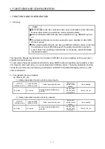
Page 41: ...1 FUNCTIONS AND CONFIGURATION 1 28 MEMO ...

Page 42: ...r and MR D30 Isolate them from all impact loads Do not install or operate the servo amplifier and MR D30 which have been damaged or have any parts missing When the product has been stored for an extended period of time contact your local sales office When handling the servo amplifier and MR D30 be careful about the edged parts such as corners of them The servo amplifier and MR D30 must be installe...

Page 43: ...irection and clearances of the MR J4 DU_ RJ refer to MR CV_ MR CR55K_ MR J4DU_ RJ Instruction Manual 1 Installation clearances of the servo amplifier a Installation of one servo amplifier 40 mm or more 10 mm or more 10 mm or more Note 2 40 mm or more Note 1 Servo amplifier Cabinet Cabinet 80 mm or more Wiring allowance Top Bottom Note 1 For the 11 kW to 22 kW servo amplifiers the clearance between...

Page 44: ...ervo amplifiers in consideration of mounting tolerances In this case keep the ambient temperature within 0 C to 45 C or use the servo amplifier with 75 or less of the effective load ratio 100 mm or more 10 mm or more Note 2 30 mm or more 30 mm or more 40 mm or more Note 1 Cabinet Top Bottom 100 mm or more 1 mm 30 mm or more 40 mm or more Cabinet 1 mm Leaving clearance Mounting closely Note 1 For t...

Page 45: ...to operating conditions especially when the servo motor is movable 3 Check that the connector is securely connected to the servo amplifier 4 Check that the wires are not coming out from the connector 5 Check for dust accumulation on the servo amplifier 6 Check for unusual noise generated from the servo amplifier 7 Make sure that the emergency stop circuit operates properly such that an operation c...

Page 46: ...ing Do not use MR D30 if its fixing hook or clips are broken Otherwise a contact failure may be caused in the connector When attaching detaching MR D30 to from MR J4 500_ RJ to MR J4 22K_ RJ and MR J4 350_4 RJ to MR J4 22K_4 RJ servo amplifiers be careful not to drop the mounting screw in the servo amplifiers Otherwise it may cause a malfunction to the servo amplifiers When mounting MR D30 to MR J...

Page 47: ...ect the CN7 and CN9 connectors straight push the four corners of the MR D30 against the servo amplifier simultaneously and keep pushing until the clips click into place 4 Tighten the unit with the enclosed mounting screw M4 b Detachment of MR D30 1 c d a b 2 1 Remove the mounting screw 2 While pushing the clips a b c d pull out MR D30 to the arrow direction Do not pull the MR D30 without removing ...

Page 48: ...he guide holes located on the side of the servo amplifier 3 2 Clip 2 To connect the CN7 and CN9 connectors straight push the four corners of the MR D30 against the servo amplifier simultaneously and keep pushing until the clips click into place 3 Tighten the unit with the enclosed mounting screw M4 c Detachment of MR D30 b 1 2 a d c 1 Remove the mounting screw 2 While pushing the clips a b c d pul...

Page 49: ...t may cause injury The mounting screw hole on these servo amplifiers are covered and not shown at shipping When attaching the unit for the first time cut off the part a from the case after removing the side cover When cutting off the part a be careful not to damage the case of the servo amplifier After the part a is cut off inside of the servo amplifier will be exposed even after the side cover or...

Page 50: ... terminals Otherwise a burst damage etc may occur Ensure that polarity is correct Otherwise a burst damage etc may occur The surge absorbing diode installed to the DC relay for control output should be fitted in the specified direction Otherwise the emergency stop and other protective circuits may not operate DO4NB DO4PB 24 V DC MR D30 RA For sink output interface DO24VA DO24VB DO4PA Control outpu...

Page 51: ...abbreviations H W abbreviation of the connector pin No not functions H W abbreviation Pin No H W abbreviation Pin No DI1A CN10A 4 DO1A CN10A 8 DI2A CN10A 13 DO2A CN10A 17 DI3A CN10A 5 DO3A CN10A 9 DI4A CN10A 14 DO4NA CN10A 18 DI5A CN10A 6 DO1B CN10B 8 DI6A CN10A 15 DO2B CN10B 17 DI1B CN10B 4 DO3B CN10B 9 DI2B CN10B 13 DO4PB CN10B 16 DI3B CN10B 5 DI4B CN10B 14 DI5B CN10B 6 DI6B CN10B 15 For signals...

Page 52: ...he short circuit connector CN10A Note No Symbol Symbol No 10 DC24VA DC24VA DO24VA 1 11 DICOMA DICOMA 2 12 PLSA 3 13 DI2A DI1A 4 14 DI4A DI3A 5 15 DI6A DI5A 6 16 7 17 DO2A DO1A 8 18 DO3A 9 CN10B Note No Symbol Symbol No 10 DC24VB DC24VB DO24VB 1 11 DICOMB DICOMB 2 12 PLSB 3 13 DI2B DI1B 4 14 DI4B DI3B 5 15 DI6B DI5B 6 16 7 17 DO2B DO1B 8 18 DO3B 9 DO4PB DO4NB DO4PA DO4NA Note DO4PA CN10A 16 DO4NA C...

Page 53: ...DI3B DI6B DI5B 24 V DC Note 3 Note 1 2 Note 1 2 For source input interface For sink input interface Note 1 Separate all the external wires by two types CN10A and CN10B 2 Assign each input device to the following combinations of connector and pin For details of each device refer to section 4 4 1 and 4 4 2 Combination of connector and pin for input DI1A CN10A 4 DI1B CN10B 4 DI2A CN10A 13 DI2B CN10B ...

Page 54: ...ing 2 Assign each output device to the following combinations of connector and pin For details of each device refer to section 4 4 1 and 4 4 2 Combination of connector and pin for output DO1A CN10A 8 DO1B CN10B 8 DO2A CN10A 17 DO2B CN10B 17 DO3A CN10A 9 DO3B CN10B 9 DO4NA CN10A 18 DO4PB CN10B 16 3 Supply 24 V DC 10 to interfaces from outside When all the I O points are used the required current ca...

Page 55: ...not a test pulse diagnosis is executed Refer to section 4 4 1 for the test pulse diagnosis Rated current 5 mA maximum current 10 mA 1 Connection of external device Connect the output signal of external device to DI _ _ Approx 5 6 kΩ MR D30 Approx 5 6 kΩ DICOMA DI1A etc CN10A DICOMB DI1B etc CN10B 24 V DC 24V IN 0V IN Control output 1 Control output 2 External device 24 V DC 5 mA 24 V DC 5 mA 2 Swi...

Page 56: ...s is an input circuit whose photocoupler cathode side is input terminal Transmit signals from sink open collector type transistor output relay switch etc The wiring differs depending on a device to be connected and on whether or not a test pulse diagnosis is executed Refer to section 4 4 1 for the test pulse diagnosis Rated current 5 mA maximum current 10 mA 1 Connection of external device Connect...

Page 57: ...C 10 0 8 A Switch Test pulse diagnosis disabled 3 Switch connection when executing a test pulse diagnosis The pulses for diagnosis will be outputted from PLSA and PLSB Wire so that the pulse signals outputted from PLSA and PLSB pass through the switch Approx 5 6 kΩ MR D30 Approx 5 6 kΩ DC24VA PLSA DICOMA DI1A etc CN10A DC24VB PLSB DICOMB DI1B etc CN10B 24 V DC 10 0 8 A 24 V DC 10 0 8 A Switch Test...

Page 58: ...may malfunction 3 3 4 DO4NA source output and DO4NB sink output DO4NA as source output and DO4PB as sink output can be combined to use As for DO4NA when the output transistor is turned on the current will flow from the output terminal to a load As for DO4PB when the output transistor is turned on the current will flow from a load to the output terminal A lamp relay or photocoupler can be driven In...

Page 59: ... it so that the electromagnetic brake operates when SBCS SBC output turns off Using MBR of servo amplifier electromagnetic brake interlock is not necessary Refer to section 4 5 6 for the operation sequence for when using SBC function Servo amplifier DO24VB SBCS CN10B 24 V DC B2 B1 Servo motor 24 V DC Note 2 ALM Malfunction RA2 U B Note 1 RA1 DO24VA SBCS CN10A MR D30 RA1 RA2 Note 1 Create the circu...

Page 60: ...induction of the cable before grounding Partly remove the insulator of the shielded cable and ground the exposed shielded part by making contact in a large area with the cabinet You can also use clamp metal parts as shown in figure 3 2 Mask the painted internal wall of the cabinet that touches the clamp metal parts Shielded part Screw Clamp fitting Shielded cable Masked paint part Figure 3 1 The s...

Page 61: ...n in the following figure If the installation position is incorrect the ferrite core will not be effective 120 mm or less Ferrite core Installing ferrite cores to the signal input wires and cables will suppress more noise The following table lists a ferrite core as an example Model Impedance Ω Note ZCAT3035 1330 TDK 10 MHz to 100 MHz 100 MHz to 500 MHz 80 150 Note The values include wires referenc...

Page 62: ... 5 3 for details of the SS1 function Open SLS1 command SLS1C The SLS function 1 operates by the SLS1 command Pr PSA07 SLS deceleration monitoring time 1 and Pr PSA11 SLS speed 1 are used Refer to section 4 5 4 for details of the SLS function Open SLS2 command SLS2C The SLS function 2 operates by the SLS2 command Pr PSA08 SLS deceleration monitoring time 2 and Pr PSA12 SLS speed 2 are used Refer to...

Page 63: ...s is a monitor output signal meaning that the STO function is operating Refer to section 4 5 1 for details Open SOS output SOSS This is a monitor output signal meaning that the servo motor in stop state is being monitored with the SS2 SOS functions Refer to section 4 5 3 for details Open SS1 output SS1S This is a monitor output signal meaning that the SS1 function is operating Refer to section 4 5...

Page 64: ...ply Digital output I F DO4A power supply DO4PA CN10A 16 This is a power supply terminal of DO4A output signal Connect of 24 V DC external power supply Digital input I F common B DICOMB CN10B 2 CN10B 11 This is a common terminal for input signal Input 24 V DC 24 V DC 10 0 8 A for I O interface The power supply capacity varies depending on the number of I O interface points to be used For sink inter...

Page 65: ...wire Insert the wire while pressing the release button with a flat blade screwdriver with a blade width of 2 0 mm to 2 5 mm When the wire is inserted all the way remove the screw driver It is recommended using the following screwdriver manufactured by Phoenix Contact model SZS 0 4X2 5 product No 1205037 Upper row Release button Wire insertion hole Flat blade screwdriver Wire Remove the screwdriver...

Page 66: ...the servo amplifier complies with safety level Category 4 PL e SIL 3 A1 24V A2 0V 24 V 0 V FLEXB US FLEXB US 24 V 0 V X1 X2 A1 24V Q1 Q2 Q3 A2 0V WS0 CPU0 WS0 XTIO CN10A CN10B S1 CN10A CN10B DO24VA DO24VB DO_A DO_B DICOMA DI_A DICOMB DI_B CN1A CC Link IE Field Network Controller MR D30 MR J4 _GF_ RJ KM1 QX_ COM I1 I2 I3 I4 Servo motor Deceleration command KM1 Magnetic contactor S1 Safety switch Ap...

Page 67: ...ion through CC Link IE Field Network The electric wiring can be omitted CN10A CN10B CN10A CN10B DO24VA DO24VB DOXA DOXB DICOMA DI_A DICOMB DI_B CN1A CN1B MR D30 MR J4 _GF_ RJ KM1 P1 P2 P1 P2 R_SFPU R6SFM RD77GF_ NZ2GFSS2 32D CC Link IE Field Network Servo motor KM1 Magnetic contactor S1 Safety switch Control circuit Safety observation function X0 X1 T0 T1 S1 ...

Page 68: ...ith safety level Category 4 PL e SIL 3 A1 24V A2 0V 24 V 0 V FLEXB US FLEXB US 24 V 0 V X1 X2 A1 24V Q1 Q2 Q3 A2 0V WS0 CPU0 WS0 XTIO CN10A CN10B S1 CN10A CN10B DO24VA DO24VB DO_A DO_B DICOMA DI_A DICOMB DI_B CN1A CN1 2 MR D30 MR J4 _B_ RJ MR J4 DU_B_ RJ KM1 X00 COM I1 I2 I3 I4 Application Application Control circuit Safety observation function Servo motor Servo system controller IO unit QX_ Decel...

Page 69: ...ic wiring can be omitted CN10A CN10B CN10A CN10B DO24VA DO24VB DOXA DOXB DICOMA DI_A DICOMB DI_B CN1A MR D30 MR J4 _B_ RJ KM1 CN1 2 SSCNET III H MC X01 PLC X01 COM Q173DSXY S1 Control circuit Safety observation function Servo motor Drive safety integrated motion controller Motion controller Q17_DSCPU Safety signal module Q173DSXY Q173DSCPU or Q172DSCPU KM1 Magnetic contactor S1 Safety switch ...

Page 70: ...ory 4 PL e SIL 3 A1 24V A2 0V 24 V 0 V FLEXB US FLEXB US 24 V 0 V X1 X2 A1 24V Q1 Q2 Q3 A2 0V WS0 CPU0 WS0 XTIO CN10A CN10B S1 CN10A CN10B DO24VA DO24VB DO_A DO_B DICOMA DI_A DICOMB DI_B CN1A CN1 2 MR D30 MR J4 _A_ RJ MR J4 DU_A_ RJ KM1 QX_ COM I1 I2 I3 I4 Application Application Safety controller MELSEC WS series CPU module WSO CPU0 Safety I O combined module WS0 XTIO Control circuit Safety obser...

Page 71: ...NG 3 22 3 9 Power on sequence Maintain about 0 5 s to 2 s in addition to the startup time of the servo amplifier in the system using MR D30 and servo motor with functional safety for the initial diagnosis of the encoder ...

Page 72: ...ector pin No not functions H W abbreviation Pin No H W abbreviation Pin No DI1A CN10A 4 DO1A CN10A 8 DI2A CN10A 13 DO2A CN10A 17 DI3A CN10A 5 DO3A CN10A 9 DI4A CN10A 14 DO4NA CN10A 18 DI5A CN10A 6 DO1B CN10B 8 DI6A CN10A 15 DO2B CN10B 17 DI1B CN10B 4 DO3B CN10B 9 DI2B CN10B 13 DO4PB CN10B 16 DI3B CN10B 5 DI4B CN10B 14 DI5B CN10B 6 DI6B CN10B 15 ...

Page 73: ...8 Category 3 PL d SIL 2 Emergency stop push button safety switch enable switch Not required _ _ 0 0 no execution 0 no execution 1 execution Safety programmable controller Note 1 safety controller Note 1 Not required _ _ 0 0 no execution 0 no execution 1 execution Category 4 PL e SIL 3 Emergency stop push button safety switch enable switch Not required _ _ 0 0 no execution 1 execution 1 execution S...

Page 74: ...troller Note 2 safety controller Note 2 Not required _ _ 2 0 execution 0 no execution Note 3 Category 3 PL d SIL 2 Category 3 PL d SIL 2 Category 3 PL d SIL 2 Category 3 PL d SIL 2 Magnetic contactor safety relay Required _ _ 1 0 execution 0 no execution Note 3 Category 4 PL e SIL 3 Category 4 PL e SIL 3 Category 4 PL e SIL 3 Category 4 PL e SIL 3 Safety programmable controller Note 1 safety contr...

Page 75: ...tion manuals GF MR J4 _GF_ RJ Servo Amplifier Instruction Manual Motion Mode B MR J4 _B RJ Servo Amplifier Instruction Manual A MR J4 _A RJ Servo Amplifier Instruction Manual Motion Q173D S CPU Q172D S CPU Motion Controller Programming Manual Safety Observation The password is set for MR D30 to prevent changing the parameters The initial password is 000000 ...

Page 76: ...m the combination of MR D30 and servo amplifier then enable the MR D30 referring to section 4 3 3 The password is set for MR D30 to prevent changing the parameters The initial password is 000000 Section 4 3 3 In the test operation operate the servo motor at the lowest speed possible with the servo motor disconnected from the machine and check whether the servo motor rotates correctly Section 4 3 4...

Page 77: ...r parameter groups The password is set to MR D30 to prevent changing the parameters The default password is 000000 a Set a password to prevent easily changing the parameter settings of MR D30 b After the settings are changed the power needs to be cycled c After changing the settings follow the procedure to check if the parameters are correct d The parameter settings of MR D30 cannot be stored in t...

Page 78: ...eters when a password is set However changing parameter is restricted until the password is confirmed a Setting and changing password Connection to MR Configurator2 Password setting Cycling of power To set and change a password connect MR Configurator2 When the parameter protection is set input the password Set a password with MR Configurator2 Set a password using one to six digits alphanumeric Th...

Page 79: ... setting to _ _ _ 1 Until this parameter is set STO cannot be canceled due to AL 7A Parameter setting error safety observation function occurrence b Pr PSA02 Functional safety unit setting Set the items according to your system configuration The recommended parameter settings and achievable safety level differ by the system structure Refer to section 4 1 for details c Pr PSA03 SS1 SS2 monitoring d...

Page 80: ...O4_ can be switched on off forcibly and independently regardless of servo status This function is used to check the wirings of signal output etc Exercise control on the DO forced output screen of MR Configurator2 This function can be used only when Pr PSA02 Functional safety unit setting is set to _ _ _ 2 test operation mode 4 3 5 Unit replacement When an MR D30 that has already been attached to M...

Page 81: ...nput device selection DI6 CN10A CN10B Parameter Pin No H W abbreviation Pin No H W abbreviation 4 DI1A 4 DI1B Pr PSD02 Input device selection DI1 13 DI2A 13 DI2B Pr PSD03 Input device selection DI2 5 DI3A 5 DI3B Pr PSD04 Input device selection DI3 14 DI4A 14 DI4B Pr PSD05 Input device selection DI4 6 DI5A 6 DI5B Pr PSD06 Input device selection DI5 15 DI6A 15 DI6B Pr PSD07 Input device selection DI...

Page 82: ...n progress SS1 in progress SLS in progress Operation status ON OFF ON disabled OFF enabled SLS1C SLS1 command ON OFF Servo amplifier display DI1A DI1B No display An error will not occur when the mismatch time is within the permissible time Input device Mismatch permissible time 79 7 b Parameter setting For the input devices that are assigned by Pr PSD02 Input device selection DI1 to Pr PSD07 Input...

Page 83: ...gnosis execution selection 2 at start up are set to execute Additionally the diagnosis will not be executed to the pin unused pin to which an input device is not assigned with Pr PSD02 Input device selection DI1 to Pr PSD07 Input device selection DI6 DI3A DI3B DI4B DI4A DI5B DI5A DI6B DI6A STOS STO output Servo on Controller or DI Base circuit WNG Warning ON OFF ON OFF ON OFF ON OFF ON OFF ON OFF ...

Page 84: ...DI3B DI4B DI4A DI5B DI5A DI6B DI6A STOS STO output Servo on Controller or DI Base circuit Servo amplifier display WNG Warning ON OFF ON OFF ON OFF ON OFF ON OFF ON OFF ON OFF ON OFF ON OFF ON OFF ON OFF ON OFF ON OFF ON Occurring OFF Not occurring ON OFF Shut off DI2A DI2B ON OFF DI1A Power supply ON OFF Main circuit Control circuit DI1B 95 ms 95 3 Start of servo on acceptance 3 s to 4 s Diagnosis...

Page 85: ...I1B The off pulses are outputted from PLSA PLSB periodically PLSA and PLSB output the off pulses at different timing not the same time The width of off pulses can be set with Pr PSD26 Input device test pulse off time Set the parameter so that external devices such as switches are affected by the output pulses DI1B ON OFF Closed Opened ON OFF ON OFF Switch ON OFF DI1A PLSA PLSB Input device Test pu...

Page 86: ...parameters for DI1_ to DI6_ which input devices are assigned to with Pr PSD02 Input device selection DI1 to Pr PSD07 Input device selection DI6 Parameter Name PSD24 Input device Test pulse diagnosis execution selection 1 PSD25 Input device Test pulse diagnosis execution selection 2 PSD26 Input device Test pulse off time Select whether or not to execute the test pulse diagnosis with Pr PSD24 Input ...

Page 87: ...a test pulse diagnosis Set 0 888 ms or longer time than set time in Pr PSD26 Input device Test pulse off time Not executing a test pulse diagnosis Set 0 888 ms or longer time Using a device Test pulses are in superposition in the output signal of the device Set 0 888 ms or longer time than the test pulse off time outputted from the device Test pulses are not in superposition in the output signal o...

Page 88: ...he following example shows a sequence for when STOC STO command is assigned to DI1_ A delay equal to the input device noise rejection filtering time occurs in the response time from signals are inputted to input devices until the corresponding functions switch to enabled disabled STOS STO output ON OFF ON disabled OFF enabled ON OFF ON disabled OFF enabled STOC STO command ON OFF Base circuit Ener...

Page 89: ...t device Test pulse execution selection 2 Output device selection The devices can be assigned to DO1_ to DO4_ with Pr PSD08 Output device selection DO1 to Pr PSD11 Output device selection DO4 CN10A CN10B Parameter Pin No H W abbreviation Pin No H W abbreviation 8 DO1A 8 DO1B Pr PSD08 Output device selection DO1 17 DO2A 17 DO2B Pr PSD09 Output device selection DO2 9 DO3A 9 DO3B Pr PSD10 Output devi...

Page 90: ...ice Test pulse off time AL 79 6 Output device error occurs when an error is detected by the test pulse diagnosis Whether or not the test pulse diagnosis is executed to each output device can be set with Pr PSD29 Output device Test pulse execution selection b Parameter setting For the output device that is assigned by Pr PSD08 Output device selection DO1 to Pr PSD11 Output device selection DO4 set ...

Page 91: ...ervation function control by input device or by network For the safety observation function control by input device refer to section 4 4 1 4 For the safety observation function control by network refer to section 4 4 3 ON OFF ON OFF DO1A ON OFF ON OFF ON OFF ON OFF ON OFF ON OFF Power supply STOS STO output DO1B DO2A DO2B DO3A DO3B Diagnosing ON OFF ON OFF DO4NA DO4PB b At error detection If MR D3...

Page 92: ...ugh network The following shows function outputs for each bit of the safety data storage device in MR J4 _GF_ RJ 2 Setting method of CC Link IE Field Network for MR J4 _GF_ RJ POINT For the system profile CSP of MR J4 _GF_ RJ use the file version 4 or later If the parameters of MR D30 are not set Safety communication activation setting cannot be executed by the parameter processing of slave statio...

Page 93: ...he cyclic RWw RWr frame are used for the safety communication Thus to assign link device RWwn RWrn consider 16 points for offsets For RWwn6 point table No selection next station No selection add 16 points as offsets and set a value to RWw n 1 6 The following shows the number of offsets necessary for each frame Frame name Offsets for safety communication RWw 16 points RWr 16 points RX 0 points RY 0...

Page 94: ...4 GF in the network configuration diagram then select Parameter processing of slave station Select Parameter processing of slave station Select Safety communication activation setting for the executing process then click Execute Select Safety communication activation setting Click Execute ...

Page 95: ...r the safety observation function control by network calculate the transmission interval monitoring time between MR D30 and CC Link IE Field Network master module according to the Safety Application Guide Use the following values for safety remote station refresh response time SRef Motion mode I O mode Safety remote station refresh response time 8 0 ms 16 0 ms Set the safety communication communic...

Page 96: ...k IE Field Network master module and the safety refresh monitoring time to the master module 4 Safety data storing devices for MR J4 _GF_ RJ a Function input The following shows the function inputs for each bit of the safety data storing devices Master station Servo amplifier SA n Bit Function input Description 0 STO command When the STO command is turned off the STO function of the servo amplifie...

Page 97: ...f under other conditions 9 SLS2 status When the SLS2 function operates the status turns on The status is off under other conditions 10 SLS3 status When the SLS3 function operates the status turns on The status is off under other conditions 11 SLS4 status When the SLS4 function operates the status turns on The status is off under other conditions 12 SS1 status When the SS1 function operates the sta...

Page 98: ...back fixing diagnosis function generates AL 79 8 Position feedback fixing error to make the servo amplifier STO state when position data from the encoder is fixed 2 Operation summary The position feedback fixing diagnosis function will be enabled when the safety observation function is enabled and moreover the servo amplifier is not in STO state When a position feedback does not change for the tim...

Page 99: ...or stops 2 Operation sequence a STOC STO command Turn off STOC STO command only when the servo motor stops after servo off The STO function will operate when STOC STO command is turned off While STO is in operation the power to the servo motor is shut off and the dynamic brake activates Turning STOC STO command back to on will return to normal operation STOS STO output 50 r min 0 r min ON disabled...

Page 100: ...urn off STOC STO command only when the servo motor stops after servo off AL 63 STO timing error occurs if STOC STO command is turned off during operation Use the SS1 function when decelerating at the same time 50 r min 0 r min Servo motor speed STO status Ordinary operation STOC STO command STOS STO output ON disabled OFF enabled Base circuit Energy supply to the servo motor ON alarm OFF no alarm ...

Page 101: ...ws operation sequence of the SS1 function The SS1 function will operate when SS1C SS1 command is turned off The servo motor decelerates with the dynamic brake electronic dynamic brake or forced stop Simultaneously the time from activation of the SS1 function is calculated and the STO function will operate when the time specified with PSA03 SS1 SS2 monitoring deceleration time has passed Turning SS...

Page 102: ...e servo motor during SS1 function operation For the operation sequence of the each stop method refer to b to d Servo amplifier parameter Servo amplifier capacity Control mode during SS1 function operation Stop method Note 1 Activated by SS1C SS1 command Activated by alarm occurrence Note 2 Pr PA04 Forced stop deceleration function selection Pr PF06 Electronic dynamic brake selection When the stop ...

Page 103: ...ctivated after the delay time specified with Pr PC02 Electromagnetic brake sequence output has passed When SS1 SS2 monitoring deceleration time is shorter than the actual deceleration time to a stop the STO function operates during the deceleration ON disabled OFF enabled ON OFF shut off ON disabled OFF enabled ON OFF Base circuit Energy supply to the servo motor STOS STO output SS1C SS1 command M...

Page 104: ...pped with the electric dynamic brake When the time has passed after the SS1 function start reaches the setting of Pr PF12 Electronic dynamic brake operating time the dynamic brake will be activated If the setting of Pr PSA03 SS1 SS2 monitoring deceleration time is shorter than that of Pr PF12 Electronic dynamic brake operating time the dynamic brake will be activated at the moment of reaching the ...

Page 105: ...cted SS2 2 Summary of sequence The SS2 SOS function will operate when SS2C SS2 command is turned off The SS2 SOS function executes monitoring deceleration at first Next it will wait until the speed decelerates to a fixed speed or until a specified time passes During this time execute deceleration with the controller Refer to 3 in this section for details of speed observation and delay time observa...

Page 106: ... ON observation in progress OFF ON disabled 0 r min OFF enabled Servo motor speed SS2C SS2 command Stop observation SOS Deceleration SS1 SS2 monitoring deceleration time Standstill speed Command Feedback Speed detection delay time b Delay time observation during deceleration When the time after starting SS2 SOS function reaches the set time of Pr PSA03 SS1 SS2 Deceleration observation time the dec...

Page 107: ...N OFF ON OFF shut off ON observation in progress OFF Base circuit Energy supply to the servo motor STOS STO output SOSS SOS output STO status Feedback Command b Speed feedback observation This observes that an absolute value of the speed feedback does not exceed the set value of Pr PSA04 SS2 SOS standstill speed during the stop observation When an excess of speed feedback continues for the set val...

Page 108: ...s When using the SS2 SOS function in the safety observation function control by network refer to 4 4 3 to set parameters Additionally when using SS2S SS2 output and SOSS SOS output with output devices refer to 4 4 2 to set parameters To use the SS2 SOS function a servo motor with functional safety is required Refer to section 4 4 4 for servo motors with functional safety When using the SS2 SOS fun...

Page 109: ...arts when SLS_C SLS command is turned off Speed observation will be started when the delay time specified with the parameter has passed after SLS_C SLS command is turned off During the speed observation the servo motor speed is observed to be equal to or less than the SLS speed specified with the parameter The speed observation will be terminated by turning on SLS_C SLS command ON disabled OFF ena...

Page 110: ...tion time 1 SLS monitoring deceleration time 2 SLS speed 1 SLS speed 2 Valid threshold 4 Speed observation a Speed command observation During the speed observation an absolute value of the speed command is observed not to exceed the SLS speed The STO function operates when the speed command exceeding the SLS speed is detected However when the speed is higher than the SLS speed the STO function wil...

Page 111: ...arameter Name PSA07 SLS deceleration monitoring time 1 PSA08 SLS deceleration monitoring time 2 PSA09 SLS deceleration monitoring time 3 PSA10 SLS deceleration monitoring time 4 PSA11 SLS speed 1 PSA12 SLS speed 2 PSA13 SLS speed 3 PSA14 SLS speed 4 PSA15 SLS SS2 SOS speed detection delay time a SLS deceleration monitoring time 1 to SLS deceleration monitoring time 4 Set a time from SLS_C SLS comm...

Page 112: ... values of both the speed command and the speed feedback are decreased exceeding the setting value of Pr PSA19 SSM hysteresis width from the SSM speed Setting Pr PSA19 SSM hysteresis width properly prevents chattering of SSMS SSM output at the time of the servo motor speed change around the SSM speed SSMS SSM output ON 0 r min OFF SSM speed Servo motor speed Feedback Command SSM hysteresis width 3...

Page 113: ...supply to the servo motor STOS STO output SBCS SBC output Electromagnetic brake ON OFF shut off Release delay time of electromagnetic brake Electromagnetic brake operation delay time 95 ms ON disabled OFF enabled MBR Electromagnetic brake interlock ON disabled OFF enabled ON disabled 0 r min OFF enabled ON OFF ON OFF ON OFF Release Operation WNG Warning Servo motor speed SS1C SS1 command Servo on ...

Page 114: ...are multiple operation triggers for a function and at least one of them is valid the function will start The following shows an operation sequence for when an alarm occurs during the operation of SS1 by SS1C SS1 command as an example STOS STO output ON disabled OFF enabled ON disabled 0 r min OFF enabled ON no alarm OFF alarm Disabled Enabled Operation of SS1 Servo motor speed SS1C SS1 command ALM...

Page 115: ...d refer to section 7 and take the appropriate action 1 Summary a Stop method The following stop methods are available when MR D30 is used Stop method Explanation DB Stops with dynamic brake Coasts for the servo amplifier without dynamic brake EDB 600 W or less servo amplifiers Stops with electronic dynamic brake 700 W or more servo amplifiers Stops with dynamic brake SD The forced stop deceleratio...

Page 116: ...alarm occurrence is removed and alarm reset is executed with all the enabled input devices on STO will be canceled returning to a normal operation It is no problem if the pin unused pin to which an input device is not assigned with Pr PSD02 Input device selection DI1 to Pr PSD07 Input device selection DI6 is off DI3A DI3B DI4B DI4A DI5B DI5A DI6B DI6A STOS STO output ALM Malfunction ON OFF ON OFF ...

Page 117: ...LS1C SLS1 command SLS2C SLS2 command SLS3C SLS3 command and SLS4C SLS4 command STO will be canceled returning to a normal operation ON disabled OFF enabled ON disabled OFF enabled ON disabled OFF enabled ON disabled OFF enabled ON disabled OFF enabled ON disabled OFF enabled ON disabled OFF enabled ON no alarm OFF alarm ON OFF Shut off SLS2C SLS2 command SLS3C SLS3 command SLS4C SLS4 command STOS ...

Page 118: ...servo amplifiers refer to each servo amplifier instruction manual 5 1 Parameter list POINT The parameter whose symbol is preceded by is enabled with the following conditions After setting the parameter cycle the power or reset the controller After setting the parameter cycle the power Abbreviations of operation modes indicate the followings Servo motor Standard semi closed loop system use of the s...

Page 119: ...ration monitoring time 3 1000 ms PSA10 SLSDT4 SLS deceleration monitoring time 4 1000 ms PSA11 SLSS1 SLS speed 1 50 r min PSA12 SLSS2 SLS speed 2 50 r min PSA13 SLSS3 SLS speed 3 50 r min PSA14 SLSS4 SLS speed 4 50 r min PSA15 SLST SLS SS2 SOS speed detection delay time 10 ms PSA16 For manufacturer setting 0000h PSA17 SOSPT SOS position detection delay time 0 ms PSA18 SSMS SSM speed 50 r min PSA19...

Page 120: ...ssword protection Input mode Operation mode Safety observation function control by network Safety observation function control by input device Servo motor Servo motor with functional safety Lin Full DD PSC01 SNC Safety communication Communication cycle 0006h PSC02 SNAS Safety communication Axis number selection 0000h PSC03 SNPOL Safety communication Servo motor rotation direction selection with fu...

Page 121: ... PSC24 0000h PSC25 0000h PSC26 0000h PSC27 0000h PSC28 0000h PSC29 0000h PSC30 0000h PSC31 0000h PSC32 0000h PSC33 0000h PSC34 0000h PSC35 0000h PSC36 0000h PSC37 0000h PSC38 0000h PSC39 0000h PSC40 0000h PSC41 0000h PSC42 0000h PSC43 0000h PSC44 0000h PSC45 0000h PSC46 0000h PSC47 0000h PSC48 0000h PSC49 0000h PSC50 0000h PSC51 0000h PSC52 0000h PSC53 0000h PSC54 0000h PSC55 0000h PSC56 0000h PSC...

Page 122: ...IF4 Input device Noise rejection filtering time DI4 0001h PSD16 SDIF5 Input device Noise rejection filtering time DI5 0001h PSD17 SDIF6 Input device Noise rejection filtering time DI6 0001h PSD18 SDIDT1 Mismatch permissible time DI1 20 ms PSD19 SDIDT2 Mismatch permissible time DI2 20 ms PSD20 SDIDT3 Mismatch permissible time DI3 20 ms PSD21 SDIDT4 Mismatch permissible time DI4 20 ms PSD22 SDIDT5 M...

Page 123: ...rol by network Safety observation function control by input device Servo motor Servo motor with functional safety Lin Full DD PSD50 For manufacturer setting 0000h PSD51 0000h PSD52 0000h PSD53 0000h PSD54 0000h PSD55 0000h PSD56 0000h PSD57 0000h PSD58 0000h PSD59 0000h PSD60 0000h PSD61 0000h PSD62 0000h PSD63 0000h PSD64 0000h ...

Page 124: ...ttings of MR D30 functions Setting digit Explanation Initial value Setting range _ _ _ x Input mode selection 0 Safety observation function control by input device 1 Safety observation function control by network 2 Test operation Please note that the safety observation function will not operate while test operation is selected For the test operation refer to each servo amplifier instruction manual...

Page 125: ...deviation will be clamped at 100 rev when Pr PSA06 SOS allowance value of position deviation unit selection is set to 0 This parameter is available with MR D30 with software version A1 or later For MR J4 _A_ RJ and MR J4 _B_ RJ this parameter is available with the servo amplifiers with software version B5 or later 3 rev Note 0 to 1000 Note Setting unit can be changed in Pr PSA06 PSA06 SAOP1 SOS al...

Page 126: ...r than the standstill speed during the speed observation of the SS2 SOS function until the stop observation SOS starts This function is available with MR D30 with software version A1 or later For MR J4 _A_ RJ and MR J4 _B_ RJ this function is available with the servo amplifiers with software version B5 or later Time after the speed accelerates higher than standstill speed during the stop observati...

Page 127: ... rev 0 to 9999 PSA22 SAADT Position feedback fixing error detection time Set a time until AL 79 8 Position feedback fixing error is detected Setting 0 will disable a diagnosis for AL 79 8 Position feedback fixing error In addition when servo motors with functional safety are used detection of AL 79 8 is not performed 60 min 0 to 65535 5 2 2 Network parameters Pr PSC_ _ No Symbol Name and function ...

Page 128: ...Setting range _ _ x x Safety communication Axis number selection Refer to table 5 1 for settings Set the same axis No as the setting of servo amplifier Setting a different No will trigger AL 7A 3 Parameter combination error safety observation function For axis No selection of servo amplifiers refer to each servo amplifier instruction manual 00h 00h to 77h _ x _ _ For manufacturer setting 0h x _ _ ...

Page 129: ...n with functional safety Refer to table 5 2 for settings 0h 0h to 1h _ _ x _ For manufacturer setting 0h _ x _ _ 0h x _ _ _ 0h Table 5 2 Servo motor rotation direction selection with functional safety Setting value Servo motor rotation direction with functional safety When forward rotation pulse is inputted When reverse rotation pulse is inputted _ _ _ 0 CCW CW _ _ _ 1 CW CCW Incorrect setting of ...

Page 130: ...c activation _ _ x _ For manufacturer setting 0h _ x _ _ 0h x _ _ _ 0h Incorrect setting of this parameter will trigger AL 7A 3 Refer to section 7 2 for details PSD02 SDI1 Input device selection DI1 Select an input device to assign to DI1A CN10A 4 and DI1B CN10B 4 When you set Safety observation function control by input device with Pr PSA02 be sure to assign one or more device to Pr PSD02 to Pr P...

Page 131: ...07h _ x _ _ For manufacturer setting 0h x _ _ _ 0h Incorrect setting of this parameter will trigger AL 7A 3 Refer to section 7 2 for details PSD05 SDI4 Input device selection DI4 Select an input device to assign to DI4A CN10A 14 and DI4B CN10B 14 Setting method is the same as Pr PSD02 Setting digit Explanation Initial value Setting range _ _ x x Input device selection DI4 Refer to table 5 3 for se...

Page 132: ... 4 for setting 00h 00h to 0Ah _ x _ _ For manufacturer setting 0h x _ _ _ 0h Table 5 4 Output device selection Setting value Output device _ _ 0 0 None _ _ 0 1 STOS STO output _ _ 0 2 SS1S SS1 output _ _ 0 3 SS2S SS2 output _ _ 0 4 SLS1S SLS1 output _ _ 0 5 SLS2S SLS2 output _ _ 0 6 SLS3S SLS3 output _ _ 0 7 SLS4S SLS4 output _ _ 0 8 SSMS SSM output _ _ 0 9 SOSS SOS output _ _ 0 A SBCS SBC output ...

Page 133: ... _ x _ _ For manufacturer setting 0h x _ _ _ 0h Incorrect setting of this parameter will trigger AL 7A 3 Refer to section 7 2 for details PSD11 SDO4 Output device selection DO4 Select an output device to assign to DO4NA CN10A 18 and DO4PB CN10B 16 Setting method is the same as Pr PSD08 Setting digit Explanation Initial value Setting range _ _ x x Output device selection DO4 Refer to table 5 4 for ...

Page 134: ...time in Pr PSD26 Input device Test pulse off time Not executing a test pulse diagnosis Set 0 888 ms or longer time Using a device which has diagnosis function Test pulses are in superposition at output signal of the device Set 0 888 ms or longer time than the test pulse off time outputted from the device Test pulses are not in superposition at output signal of the device Set 0 888 ms or longer tim...

Page 135: ...05h _ x _ _ For manufacturer setting 0h x _ _ _ 0h Incorrect setting of this parameter will trigger AL 7A 3 Refer to section 7 2 for details PSD16 SDIF5 Input device Noise rejection filtering time DI5 Select a filtering time to reduce noise of DI5A CN10A 6 and DI5B CN10B 6 Setting method is the same as Pr PSD12 Setting digit Explanation Initial value Setting range _ _ x x Noise rejection filtering...

Page 136: ... ms 0 to 60000 PSD22 SDIDT5 Mismatch permissible time DI5 Set a threshold of mismatch time of DI5A CN10A 6 and DI5B CN10B 6 When the mismatch time of DI5A and DI5B reaches the setting value AL 79 7 Mismatched input signal error will occur Setting 0 disables alarm detections 20 ms 0 to 60000 PSD23 SDIDT6 Mismatch permissible time DI6 Set a threshold of mismatch time of DI6A CN10A 15 and DI6B CN10B ...

Page 137: ... off time 1 0 888 ms 2 1 777 ms 1h 1h to 2h _ _ x _ For manufacturer setting 0h _ x _ _ 0h x _ _ _ 0h Incorrect setting of this parameter will trigger AL 7A 3 Refer to section 7 2 for details PSD27 SDID1 Input device Fixing diagnosis execution selection 1 at start up Select whether or not to execute a fixing diagnosis of DI1_ to DI4_ at start up Setting digit Explanation Initial value Setting rang...

Page 138: ...Output device Test pulse execution selection Select whether or not to diagnose DO1_ to DO4_ by test pulses Selecting 0 Not diagnose will not transmit the test pulses from DO1_ to DO4_ Setting digit Explanation Initial value Setting range _ _ _ x Test pulse diagnosis execution selection DO1 Select whether or not to diagnose DO1_ by test pulses 0 Not diagnose 1 Diagnose 1h 0h to 1h _ _ x _ Test puls...

Page 139: ...off pulse time outputted from DO1_ Refer to table 5 6 for settings 0h 0h to 2h _ _ x _ Test pulse off time DO2 Select off pulse time outputted from DO2_ Refer to table 5 6 for settings 0h 0h to 2h _ x _ _ Test pulse off time DO3 Select off pulse time outputted from DO3_ Refer to table 5 6 for settings 0h 0h to 2h x _ _ _ Test pulse off time DO4 Select off pulse time outputted from DO4_ Refer to ta...

Page 140: ...the software version of a servo amplifier that is compatible with MR D30 The following shows indication example of each state POWER RUN STO ERROR Servo amplifier display Status Description Normal Power off Power is not supplied 95 _ or Ab During diagnosis For the safety observation function control by input device execute a fixing diagnosis at start up For the safety observation function control b...

Page 141: ...6 DISPLAY 6 2 MEMO ...

Page 142: ...and warnings are not recorded in the alarm history 7 1 Alarm and warning list The following shows alarms and warnings which are added for the functional safety unit When the alarm or the warning occurs refer to MELSERVO J4 Servo Amplifier Instruction Manual Troubleshooting to remove the failure When an alarm occurs ALM Malfunction will be off After its cause has been removed the alarm can be deact...

Page 143: ...munication Receive data error 2 safety observation function DB 66 3 Encoder initial communication Receive data error 3 safety observation function DB 66 7 Encoder initial communication Transmission data error 1 safety observation function DB 66 9 Encoder initial communication Process error safety observation function DB 67 1 Encoder communication Receive data error 1 safety observation function DB...

Page 144: ... specified servo motors Refer to the following table for the specified servo motors The stop method for other than the specified servo motors is SS1 DB Series Servo motor HG KR HG KR053 HG KR13 HG KR23 HG KR43 HG MR HG MR053 HG MR13 HG MR23 HG MR43 HG SR HG SR51 HG SR52 2 This is applicable when Pr PA04 is set to the initial value The stop system of SD can be changed to DB using Pr PA04 Pr PA04 is...

Page 145: ... to _ _ 0 8 _ _ 0 A Pr PSA20 Servo motor encoder resolution Lower Pr PSA21 Servo motor encoder resolution Upper Set the servo motor encoder resolution Set the servo motor encoder resolution Pr PSC03 Safety communication Servo motor rotation direction selection with functional safety Set the same value as that of Pr PA14 of the servo amplifier Motor less operation Impossible Possible Note 1 Set a v...

Page 146: ...onal safety unit Unit mm 20 28 95 4 99 2 104 2 161 97 24 5 114 5 Rating plate Four fixing screws for connectors Tightening torque 0 2 N m to 0 3 N m Mounting screw Screw size M4 Tightening torque 1 65 N m 5 6 mounting hole for grounding Mass 0 15 kg ...

Page 147: ...R D30 100 V 200 V 0 1 kW to 3 5 kW 400 V 0 6 kW to 2 kW 200 V 5 kW 7 kW 400 V 3 5 kW to 7 kW Servo amplifier L mm MR J4 10_1 RJ to MR J4 40_1 RJ MR J4 10_ RJ to MR J4 100_ RJ MR J4 60_4 RJ to MR J4 100_4 RJ 20 MR J4 200_ RJ MR J4 350_ RJ MR J4 200_4 RJ 15 MR J4 500_ RJ MR J4 700_ RJ MR J4 350_4 RJ to MR J4 700_4 RJ 10 MR J4 11K_ RJ to MR J4 22K_ RJ MR J4 11K_4 RJ to MR J4 22K_4 RJ MR J4 DU30K_ RJ ...

Page 148: ...id down in the machinery directive When the servo motor with functional safety is not used some functions are rated SIL 2 PL d category 3 indicated with with Non safety encoder in the certificate The functions described in the certificate are unusable unless otherwise explained in this instruction manual ...

Page 149: ...4 1 Section 4 3 4 2 Section 4 4 1 1 d Section 4 4 1 2 a The diagram is added The table is changed The sentences are changed The table is changed Added The diagram is changed Added POINT is added Added The table is changed The table is changed Sentences of POINT and table are changed The sentences are changed The sentences are changed The sentences in POINT are changed The sentences of Note are cha...

Page 150: ...entences and diagram are changed The sentences are changed Deleted Added Added The sentences and diagram are changed The sentences and diagram are changed The sentences and diagram are changed The sentences and diagram are changed The sentences and diagram are changed The sentences and diagram are changed The sentences and diagram are changed The sentences and diagram are changed The sentences and...

Page 151: ...changed Section 5 2 2 The sentences are added to PSC01 to PSC03 PSC04 is added Section 5 2 3 The sentences are added to PSD01 to PSD17 and PSD26 Chapter 6 The notes of the table are changed Section 7 2 Added Section 8 2 POINT is added The table is changed App 1 The certificate is updated Apr 2017 SH NA 030132ENG D The description of the safety observation function control by network is added for M...

Page 152: ... Section 8 6 Partially added Section 8 7 Partially added Section 8 8 1 Partially added Section 8 8 2 Partially added App 4 Partially added App 6 Partially added This manual confers no industrial property rights or any rights of any other kind nor does it confer any patent licenses Mitsubishi Electric Corporation cannot be held responsible for any problems involving industrial property rights which...

Page 153: ...MEMO ...

Page 154: ...a trademark or registered trademark of Mitsubishi Electric Corporation in Japan and or other countries All other product names and company names are trademarks or registered trademarks of their respective companies ...

Page 155: ...ct from our company viii any other failures which we are not responsible for or which you acknowledge we are not responsible for 2 Term of warranty after the stop of production 1 We may accept the repair at charge for another seven 7 years after the production of the product is discontinued The announcement of the stop of production for each model can be seen in our Sales and Service etc 2 Please ...

Page 156: ... change without notice This Instruction Manual uses recycled paper MODEL MODEL CODE General Purpose AC Servo MR D30 INSTRUCTION MANUAL HEAD OFFICE TOKYO BLDG MARUNOUCHI TOKYO 100 8310 1CW817 MR D30 INSTRUCTIONMANUAL Functional safety unit MODEL MR D30 INSTRUCTION MANUAL E E ...

Reviews: