WWW.NNC.IR
3 - 60
3. SIGNALS AND WIRING
3.10 Grounding
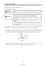
WARNING
Ground the servo amplifier and servo motor securely.
To prevent an electric shock, always connect the protective earth (PE) terminal of
the servo amplifier with the protective earth (PE) of the control box.
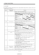
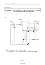
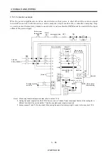
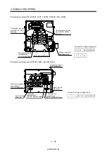
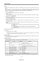
The servo amplifier switches the power transistor on-off to supply power to the servo motor. Depending on
the wiring and ground cable routing, the servo amplifier may be affected by the switching noise (due to
di/dt and dv/dt) of the transistor. To prevent such a fault, refer to the following diagram and always
ground.
To conform to the EMC Directive, refer to the EMC Installation Guidelines (IB(NA)67310).
Control box
Servo amplifier
L
1
L
2
L
3
L
11
L
21
CN1A CN1B
Li
ne
fi
lter
NFB
MC
Protective earth(PE)
CN2
U
V
W
Outer
box
Servo motor
Ensure to connect it to PE
terminal of the servo amplifier.
Do not connect it directly to
the protective earth of
the control panel.
Encoder
M
U
V
W
(Note)
Power supply
Pr
og
ra
mma
b
le
cont
roller
Note. For 1-phase 230VAC, connect the power supply to L
1
L
2
and leave L
3
open.
There is no L
3
for 1-phase 100 to 120VAC power supply. Refer to section 1.3 for the power supply specification.
Summary of Contents for MR-J2S-*A
Page 13: ...WWW NNC IR A 12 MEMO ...
Page 117: ...WWW NNC IR 3 70 3 SIGNALS AND WIRING MEMO ...
Page 185: ...WWW NNC IR 7 12 7 GENERAL GAIN ADJUSTMENT MEMO ...
Page 195: ...WWW NNC IR 8 10 8 SPECIAL ADJUSTMENT FUNCTIONS MEMO ...
Page 197: ...WWW NNC IR 9 2 9 INSPECTION MEMO ...
Page 221: ...WWW NNC IR 11 10 11 OUTLINE DIMENSION DRAWINGS MEMO ...
Page 293: ...WWW NNC IR 13 64 13 OPTIONS AND AUXILIARY EQUIPMENT MEMO ...
Page 321: ...WWW NNC IR 14 28 14 COMMUNICATION FUNCTIONS MEMO ...
Page 389: ...WWW NNC IR 15 68 15 ABSOLUTE POSITION DETECTION SYSTEM MEMO ...

