WWW.NNC.IR
4 - 3
4. OPERATION
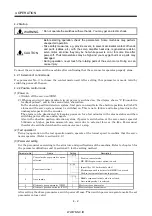
(4) Servo-on
Switch the servo-on in the following procedure.
1) Switch on main circuit/control circuit power supply.
2) Switch on the servo-on (SON)
When placed in the servo-on status, the servo amplifier is ready to operate and the servo motor
is locked.
(5) Command pulse input
Entry of a pulse train from the positioning device rotates the servo motor. At first, run it at low speed
and check the rotation direction, etc. If it does not run in the intended direction, check the input
signal.
On the status display, check the speed, command pulse frequency, load factor, etc. of the servo motor.
When machine operation check is over, check automatic operation with the program of the positioning
device.
This servo amplifier has a real-time auto tuning function under model adaptive control. Performing
operation automatically adjusts gains. The optimum tuning results are provided by setting the
response level appropriate for the machine in parameter No. 2. (Refer to chapter 7)
(6) Home position return
Make home position return as required.
(7) Stop
In any of the following statuses, the servo amplifier interrupts and stops the operation of the servo
motor.
Refer to section 3.9, (2) for the servo motor equipped with electromagnetic brake. Note that the stop
pattern of stroke end (LSP/LSN) OFF is as described below.
(a) Servo-on (SON) OFF
The base circuit is shut off and the servo motor coasts.
(b) Alarm occurrence
When an alarm occurs, the base circuit is shut off and the dynamic brake is operated to bring the
servo motor to a sudden stop.
(c) Emergency stop (EMG) OFF
The base circuit is shut off and the dynamic brake is operated to bring the servo motor to a sudden
stop. Alarm AL.E6 occurs.
(d) Forward rotation stroke end (LSP), reverse rotation stroke end (LSN) OFF
The droop pulse value is erased and the servo motor is stopped and servo-locked. It can be run in
the opposite direction.
Summary of Contents for MR-J2S-*A
Page 13: ...WWW NNC IR A 12 MEMO ...
Page 117: ...WWW NNC IR 3 70 3 SIGNALS AND WIRING MEMO ...
Page 185: ...WWW NNC IR 7 12 7 GENERAL GAIN ADJUSTMENT MEMO ...
Page 195: ...WWW NNC IR 8 10 8 SPECIAL ADJUSTMENT FUNCTIONS MEMO ...
Page 197: ...WWW NNC IR 9 2 9 INSPECTION MEMO ...
Page 221: ...WWW NNC IR 11 10 11 OUTLINE DIMENSION DRAWINGS MEMO ...
Page 293: ...WWW NNC IR 13 64 13 OPTIONS AND AUXILIARY EQUIPMENT MEMO ...
Page 321: ...WWW NNC IR 14 28 14 COMMUNICATION FUNCTIONS MEMO ...
Page 389: ...WWW NNC IR 15 68 15 ABSOLUTE POSITION DETECTION SYSTEM MEMO ...


