WWW.NNC.IR
5 - 11
5. PARAMETERS
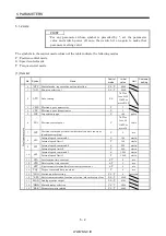
Class No. Symbol
Name and function
Initial
value
Unit
Setting
range
Control
mode
B
asi
c pa
ra
m
et
ers
17
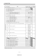
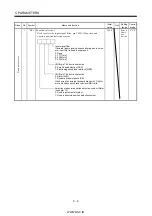
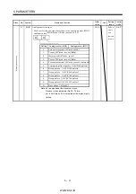
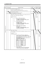
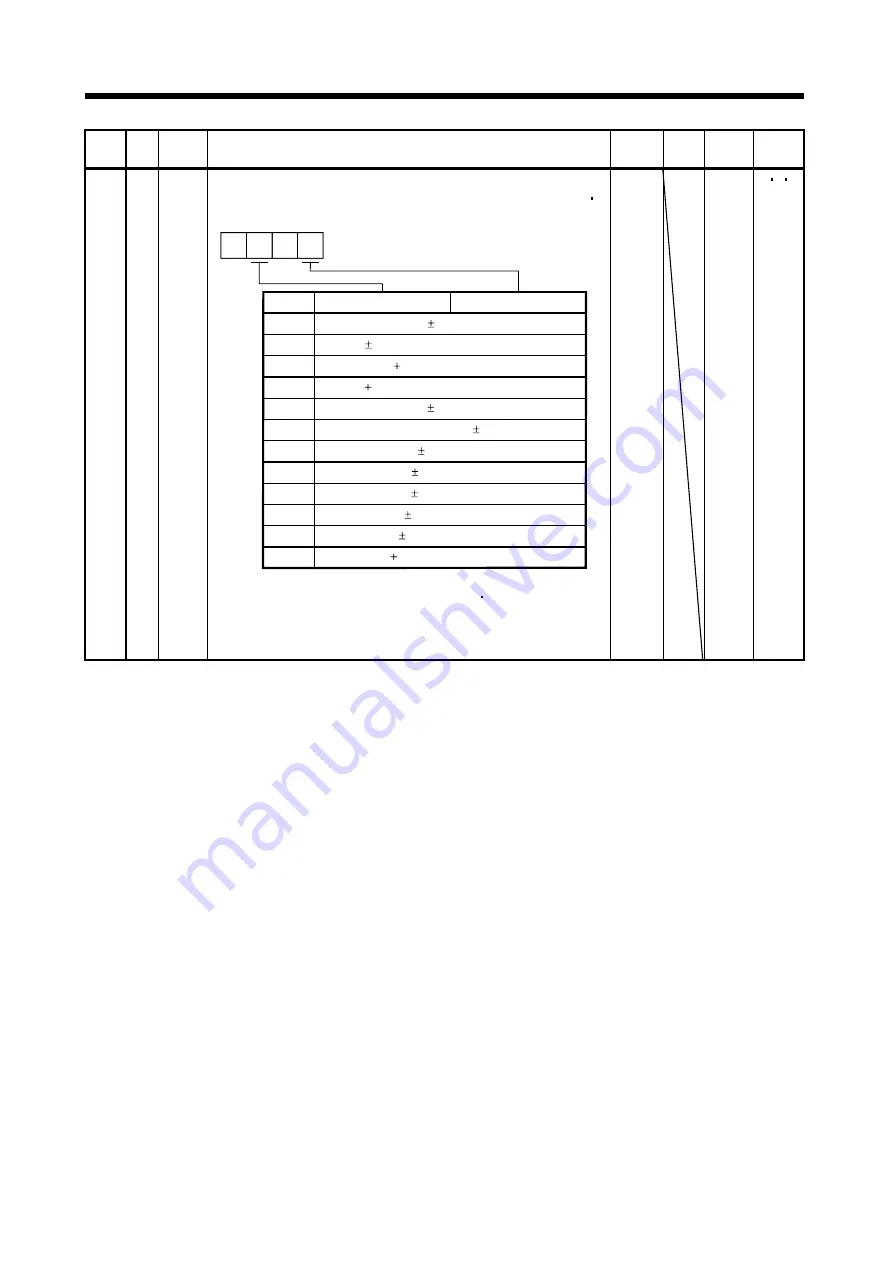
MOD Analog monitor output
Used to selection the signal provided to the analog monitor (MO1)
analog monitor (MO2) output. (Refer to section 5.2.2)
Setting
0
Analog monitor (MO2)
Servo motor speed ( 8V/max. speed)
1
Torque ( 8V/max. torque)
(Note)
2
Motor speed ( 8V/max. speed)
3
Torque ( 8V/max. torque)
(Note)
4
Current command ( 8V/max. current command)
5
Command pulse frequency ( 10V/500kpulse/s)
6
Droop pulses ( 10V/128 pulses)
7
Droop pulses ( 10V/2048 pulses)
8
Droop pulses ( 10V/8192 pulses)
9
Droop pulses ( 10V/32768 pulses)
A
Droop pulses ( 10V/131072 pulses)
0
0
B
Bus voltage ( 8V/400V)
Analog monitor (MO1)
Note. 8V is outputted at the maximum torque.
However, when parameter No.28 76 are
set to limit torque, 8V is outputted at the torque highly
limited.
0100
Refer to
Name
and
function
column.
P S T
Summary of Contents for MR-J2S-*A
Page 13: ...WWW NNC IR A 12 MEMO ...
Page 117: ...WWW NNC IR 3 70 3 SIGNALS AND WIRING MEMO ...
Page 185: ...WWW NNC IR 7 12 7 GENERAL GAIN ADJUSTMENT MEMO ...
Page 195: ...WWW NNC IR 8 10 8 SPECIAL ADJUSTMENT FUNCTIONS MEMO ...
Page 197: ...WWW NNC IR 9 2 9 INSPECTION MEMO ...
Page 221: ...WWW NNC IR 11 10 11 OUTLINE DIMENSION DRAWINGS MEMO ...
Page 293: ...WWW NNC IR 13 64 13 OPTIONS AND AUXILIARY EQUIPMENT MEMO ...
Page 321: ...WWW NNC IR 14 28 14 COMMUNICATION FUNCTIONS MEMO ...
Page 389: ...WWW NNC IR 15 68 15 ABSOLUTE POSITION DETECTION SYSTEM MEMO ...

