WWW.NNC.IR
5 - 23
5. PARAMETERS
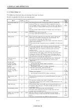
Class No. Symbol
Name and function
Initial
value
Unit
Setting
range
Control
mode
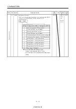
60
LPF
Low-pass filter adaptive vibration suppression control
Used to selection the low-pass filter adaptive vibration suppression
control. (Refer to chapter 8)
0
Low-pass filter selection
0: Valid (Automatic adjustment)
1: Invalid
Adaptive vibration suppression control selection
Choosing "valid" or "held" in adaptive vibration
suppression control selection makes the machine
resonance control filter 1 (parameter No. 58) invalid.
0: Invalid
1: Valid
Machine resonance frequency is always detected
and the filter is generated in response to resonance to
suppress machine vibration.
2: Held
The characteristics of the filter generated so far are held,
and detection of machine resonance is stopped.
Adaptive vibration suppression control sensitivity selection
Used to set the sensitivity of machine resonance detection.
0: Normal
1: Large sensitivity
When you choose "valid", the filter of the handwidth
represented by the following expression is set automatically
2 (1 GD2 setting 0.1)
VG2 setting 10
For 1kW or less
2 (1 GD2 setting 0.1)
VG2 setting 5
For 2kW or more
[H
z
]
[H
z
]
0000
Refer to
Name
and
function
column.
P S T
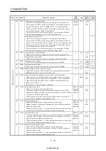
61
GD2B Ratio of load inertia moment to servo motor inertia moment 2
Used to set the ratio of load inertia moment to servo motor inertia
moment when gain changing is valid.
70
0.1
times
0
to
3000
P S
62
PG2B Position control gain 2 changing ratio
Used to set the ratio of changing the position control gain 2 when
gain changing is valid.
Made valid when auto tuning is invalid.
100
%
10
to
200
P
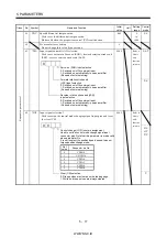
63
VG2B Speed control gain 2 changing ratio
Used to set the ratio of changing the speed control gain 2 when gain
changing is valid.
Made valid when auto tuning is invalid.
100
%
10
to
200
P S
E
xpa
n
si
on
pa
ra
m
et
ers
2
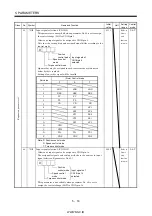
64
VICB Speed integral compensation changing ratio
Used to set the ratio of changing the speed integral compensation
when gain changing is valid. Made valid when auto tuning is invalid.
100
%
50
to
1000
P S
Summary of Contents for MR-J2S-*A
Page 13: ...WWW NNC IR A 12 MEMO ...
Page 117: ...WWW NNC IR 3 70 3 SIGNALS AND WIRING MEMO ...
Page 185: ...WWW NNC IR 7 12 7 GENERAL GAIN ADJUSTMENT MEMO ...
Page 195: ...WWW NNC IR 8 10 8 SPECIAL ADJUSTMENT FUNCTIONS MEMO ...
Page 197: ...WWW NNC IR 9 2 9 INSPECTION MEMO ...
Page 221: ...WWW NNC IR 11 10 11 OUTLINE DIMENSION DRAWINGS MEMO ...
Page 293: ...WWW NNC IR 13 64 13 OPTIONS AND AUXILIARY EQUIPMENT MEMO ...
Page 321: ...WWW NNC IR 14 28 14 COMMUNICATION FUNCTIONS MEMO ...
Page 389: ...WWW NNC IR 15 68 15 ABSOLUTE POSITION DETECTION SYSTEM MEMO ...


