WWW.NNC.IR
6 - 14
6. DISPLAY AND OPERATION
6.8.2 Jog operation
Jog operation can be performed when there is no command from the external command device.
(1) Operation
Connect EMG-SG to start jog operation and connect VDD-COM to use the internal power supply.
Hold down the
"UP"
or
"DOWN"
button to run the servo motor. Release it to stop. When using the MR
Configurator (servo configuration software), you can change the operation conditions. The initial
conditions and setting ranges for operation are listed below.
Item
Initial setting
Setting range
Speed [r/min]
200
0 to instantaneous permissible speed
Acceleration/deceleration time constant [ms]
1000
0 to 50000
How to use the buttons is explained below.
Button
Description
"UP"
Press to start CCW rotation.
Release to stop.
"DOWN"
Press to start CW rotation.
Release to stop.
If the communication cable is disconnected during jog operation performed by using the MR
Configurator (servo configuration software), the servo motor will be decelerated to a stop.
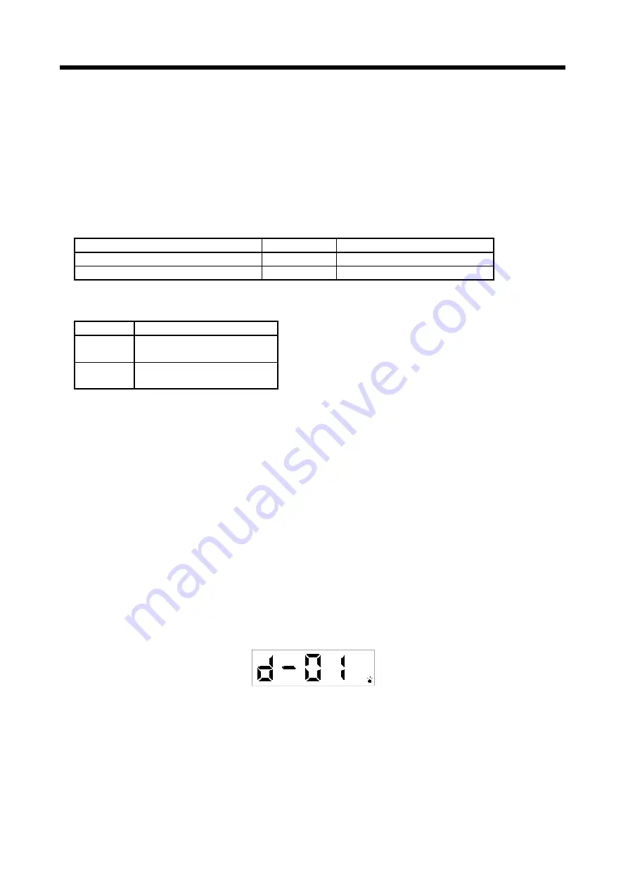
(2) Status display
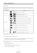
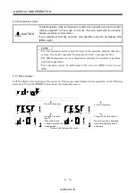
You can confirm the servo status during jog operation.
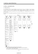
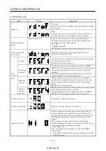
Pressing the
"MODE"
button in the jog operation-ready status calls the status display screen. With this
screen being shown, perform jog operation with the
"UP"
or
"DOWN"
button. Every time you press the
"MODE"
button, the next status display screen appears, and on completion of a screen cycle, pressing
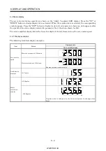
that button returns to the jog operation-ready status screen. For full information of the status display,
refer to section 6.2. In the test operation mode, you cannot use the
"UP"
and
"DOWN"
buttons to
change the status display screen from one to another.
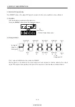
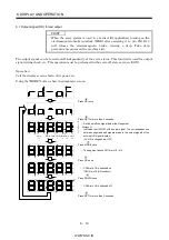
(3) Termination of jog operation
To end the jog operation, switch power off once or press the
"MODE"
button to switch to the next
screen and then hold down the
"SET"
button for 2 or more seconds.
Summary of Contents for MR-J2S-*A
Page 13: ...WWW NNC IR A 12 MEMO ...
Page 117: ...WWW NNC IR 3 70 3 SIGNALS AND WIRING MEMO ...
Page 185: ...WWW NNC IR 7 12 7 GENERAL GAIN ADJUSTMENT MEMO ...
Page 195: ...WWW NNC IR 8 10 8 SPECIAL ADJUSTMENT FUNCTIONS MEMO ...
Page 197: ...WWW NNC IR 9 2 9 INSPECTION MEMO ...
Page 221: ...WWW NNC IR 11 10 11 OUTLINE DIMENSION DRAWINGS MEMO ...
Page 293: ...WWW NNC IR 13 64 13 OPTIONS AND AUXILIARY EQUIPMENT MEMO ...
Page 321: ...WWW NNC IR 14 28 14 COMMUNICATION FUNCTIONS MEMO ...
Page 389: ...WWW NNC IR 15 68 15 ABSOLUTE POSITION DETECTION SYSTEM MEMO ...

