WWW.NNC.IR
7 - 10
7. GENERAL GAIN ADJUSTMENT
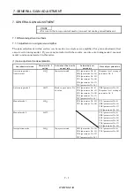
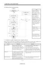
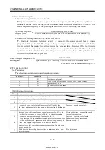
(b) Manually adjusted parameters
The following parameters are adjustable manually.
Parameter No.
Abbreviation
Name
6
PG1
Position control gain 1
36
VG1
Speed control gain 1
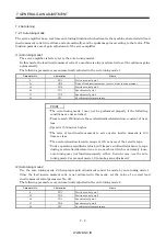
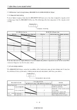
(2) Adjustment procedure
Step
Operation
Description
1
Set 15Hz (parameter No. 2: 010 ) as the machine resonance frequency of response
in the auto tuning mode 1.
Select the auto tuning mode 1.
2
During operation, increase the response level setting (parameter No. 2), and
return the setting if vibration occurs.
Adjustment in auto tuning mode
1.
3
Check the values of position control gain 1 (parameter No. 6) and speed control
gain 1 (parameter No. 36).
Check the upper setting limits.
4
Set the interpolation mode (parameter No. 2: 000 ).
Select the interpolation mode.
5
Set the position control gain 1 of all the axes to be interpolated to the same value.
At that time, adjust to the setting value of the axis, which has the smallest
position control gain 1.
Set position control gain 1.
6
Using the speed control gain 1 value checked in step 3 as the guideline of the
upper limit, look at the rotation status and set in speed control gain 1 the value
three or more times greater than the position control gain 1 setting.
Set speed control gain 1.
7
Looking at the interpolation characteristic and rotation status, fine-adjust the
gains and response level setting.
Fine adjustment.
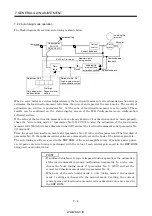
(3) Adjustment description
(a) Position control gain 1 (parameter No.6)
This parameter determines the response level of the position control loop. Increasing position
control gain 1 improves track ability to a position command but a too high value will make
overshooting liable to occur at the time of settling. The droop pulse value is determined by the
following expression.
Droop pulse value (pulse)
Position control gain 1 setting
131,072(pulse)
Rotation speed (r/min)
60
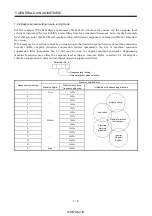
(b) Speed control gain 1 (parameter No. 36)
Set the response level of the speed loop of the model. Make setting using the following expression
as a guideline.
Speed control gain 1 setting Position control gain 1 setting 3
Summary of Contents for MR-J2S-*A
Page 13: ...WWW NNC IR A 12 MEMO ...
Page 117: ...WWW NNC IR 3 70 3 SIGNALS AND WIRING MEMO ...
Page 185: ...WWW NNC IR 7 12 7 GENERAL GAIN ADJUSTMENT MEMO ...
Page 195: ...WWW NNC IR 8 10 8 SPECIAL ADJUSTMENT FUNCTIONS MEMO ...
Page 197: ...WWW NNC IR 9 2 9 INSPECTION MEMO ...
Page 221: ...WWW NNC IR 11 10 11 OUTLINE DIMENSION DRAWINGS MEMO ...
Page 293: ...WWW NNC IR 13 64 13 OPTIONS AND AUXILIARY EQUIPMENT MEMO ...
Page 321: ...WWW NNC IR 14 28 14 COMMUNICATION FUNCTIONS MEMO ...
Page 389: ...WWW NNC IR 15 68 15 ABSOLUTE POSITION DETECTION SYSTEM MEMO ...

