WWW.NNC.IR
8 - 9
8. SPECIAL ADJUSTMENT FUNCTIONS
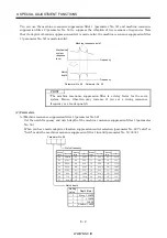
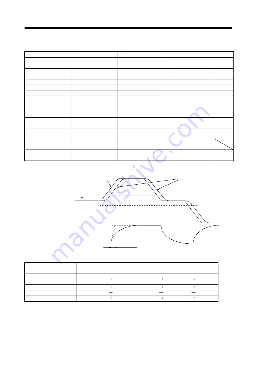
(2) When you choose changing by droop pulses
(a) Setting
Parameter No.
Abbreviation
Name
Setting
Unit
6
PG1
Position control gain 1
100
rad/s
36
VG1
Speed control gain 1
1000
rad/s
34
GD2
Ratio of load inertia moment to
servo motor inertia moment
40
0.1 times
35
PG2
Position control gain 2
120
rad/s
37
VG2
Speed control gain 2
3000
rad/s
38
VIC
Speed integral compensation
20
ms
61
GD2B
Ratio of load inertia moment to
servo motor inertia moment 2
100
0.1 times
62
PG2B
Position control gain 2
changing ratio
70
%
63
VG2B
Speed control gain 2 changing
ratio
133
%
64
VICB
Speed integral compensation
changing ratio
250
%
65
CDP
Gain changing selection
0003
(Changed by droop pulses)
66
CDS
Gain changing condition
50
pulse
67
CDT
Gain changing time constant
100
ms
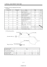
(b) Changing operation
CDT 100ms
0
Droop pulses [pulses]
Change of each gain
CDS
CDS
Before-changing gain
After-changing gain
Command pulse
Droop pulses
Position control gain 1
100
Speed control gain 1
1000
Ratio of load inertia moment
to servo motor inertia moment
4.0
10.0
4.0
10.0
Position control gain 2
120
84
120
84
Speed control gain 2
3000
4000
3000
4000
Speed integral compensation
20
50
20
50
Summary of Contents for MR-J2S-*A
Page 13: ...WWW NNC IR A 12 MEMO ...
Page 117: ...WWW NNC IR 3 70 3 SIGNALS AND WIRING MEMO ...
Page 185: ...WWW NNC IR 7 12 7 GENERAL GAIN ADJUSTMENT MEMO ...
Page 195: ...WWW NNC IR 8 10 8 SPECIAL ADJUSTMENT FUNCTIONS MEMO ...
Page 197: ...WWW NNC IR 9 2 9 INSPECTION MEMO ...
Page 221: ...WWW NNC IR 11 10 11 OUTLINE DIMENSION DRAWINGS MEMO ...
Page 293: ...WWW NNC IR 13 64 13 OPTIONS AND AUXILIARY EQUIPMENT MEMO ...
Page 321: ...WWW NNC IR 14 28 14 COMMUNICATION FUNCTIONS MEMO ...
Page 389: ...WWW NNC IR 15 68 15 ABSOLUTE POSITION DETECTION SYSTEM MEMO ...

