WWW.NNC.IR
13 - 6
13. OPTIONS AND AUXILIARY EQUIPMENT
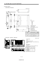
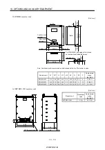
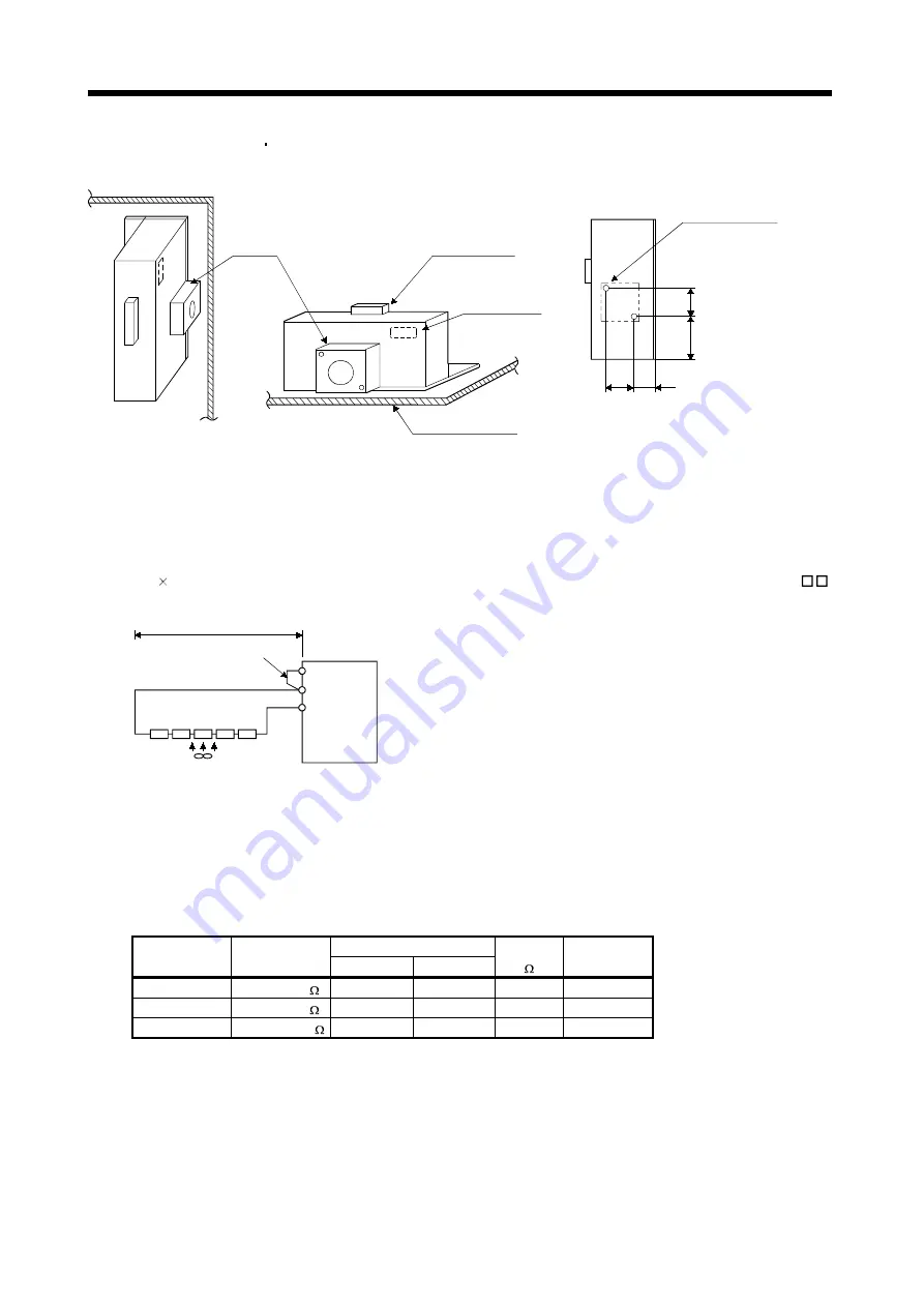
For the MR-RB50 MR-RB51 install the cooling fan as shown.
82.5
40 (1.58)
82.5
13
3
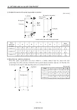
Cooling fan installation screw hole dimensions
2-M3 screw hole
(for cooling fan installation)
Depth 10 or less
(Screw hole already
machined)
Cooling fan
Terminal block
Thermal relay
Installation surface
Horizontal installation
Vertical
installation
Top
Bottom
(3
.2
5
)
(5.
24)
(3.25)
[Unit : mm(in)]
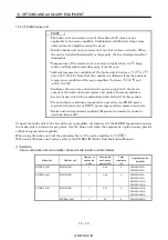
(c) MR-J2S-11KA to MR-J2S-22KA (when using the supplied regenerative resistor)
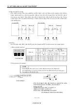
When using the regenerative resistors supplied to the servo amplifier, the specified number of
resistors (4 or 5 resistors) must be connected in series. If they are connected in parallel or in less
than the specified number, the servo amplifier may become faulty and/or the regenerative resistors
burn. Install the resistors at intervals of about 70mm. Cooling the resistors with two cooling fans
(92 92, minimum air flow : 1.0m
3
) improves the regeneration capability. In this case, set "0E "
in parameter No. 0.
P
C
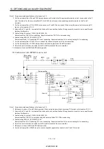
Cooling fan
5m or less
Do not remove
the short bar.
Servo amplifier
P
1
(Note) Series connection
Note. The number of resistors connected in series depends on the resistor type. Install a thermal sensor or like to configure a
circuit that will shut off the main circuit power at abnormal overheat. The supplied regenerative resistor does not have a
built-in thermal sensor. If the regenerative brake circuit fails, abnormal overheat of the resistor is expected to occur. On
the customer side, please also install a thermal sensor for the resistor and provide a protective circuit that will shut off the
main circuit power supply at abnormal overheat. The detection level of the thermal sensor changes depending on the
resistor installation method. Please install the thermal sensor in the optimum position according to the customer's design
standards, or use our regenerative option having built-in thermal sensor (MR-RB65, 66, 67).
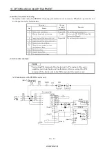
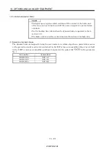
Regenerative Power [W]
Servo Amplifier
Regenerative
Resistor
Normal
Cooling
Resistance
[ ]
Number of
Resistors
MR-J2S-11KA
GRZG400-2
500
800
8
4
MR-J2S-15KA
GRZG400-1
850
1300
5
5
MR-J2S-22KA GRZG400-0.8
850
1300
4
5
Summary of Contents for MR-J2S-*A
Page 13: ...WWW NNC IR A 12 MEMO ...
Page 117: ...WWW NNC IR 3 70 3 SIGNALS AND WIRING MEMO ...
Page 185: ...WWW NNC IR 7 12 7 GENERAL GAIN ADJUSTMENT MEMO ...
Page 195: ...WWW NNC IR 8 10 8 SPECIAL ADJUSTMENT FUNCTIONS MEMO ...
Page 197: ...WWW NNC IR 9 2 9 INSPECTION MEMO ...
Page 221: ...WWW NNC IR 11 10 11 OUTLINE DIMENSION DRAWINGS MEMO ...
Page 293: ...WWW NNC IR 13 64 13 OPTIONS AND AUXILIARY EQUIPMENT MEMO ...
Page 321: ...WWW NNC IR 14 28 14 COMMUNICATION FUNCTIONS MEMO ...
Page 389: ...WWW NNC IR 15 68 15 ABSOLUTE POSITION DETECTION SYSTEM MEMO ...


