WWW.NNC.IR
15 - 32
15. ABSOLUTE POSITION DETECTION SYSTEM
M1
K1
D9
K7912
H0001
DFROP
M1
Y4B
D3
D3
D*P
Y4B
SET
K1
D3
K41
H0001
DTOP
Y49
X36
Y41
T0
Y41
Y42
Y41
X32
T0
T1
T3
4
4
D3
D9
D3
D P
M3
SET
Y41
RST
K50
T1
K10
T3
K10
Y49
(Note)
5
5
K0
D
D3
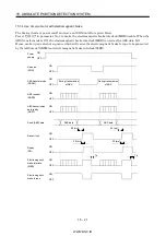
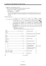
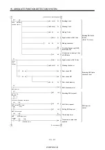
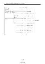
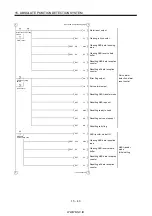
Restoring absolute
position data
Detecting ABS
coordinate error
Writing ABS data
to A1SD71
ABS communication
error detecting
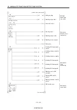
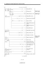
*1 A1SD71: reading home
position address
Inserting constant K for conversion
into the unit of feed per pulse
Adding home position address
to absolute position
Setting ABS coordinate error
*1 X-axis: Present position
change ABS data "ready"
ABS data "ready"
Resetting ABS transfer mode
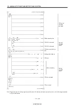
ABS transfer mode timer (5s)
ABS request response timer
(1s)
Ready to send response
timer (1s)
ABS communication error
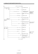
(Continued from preceding page)
(To be continued)
Checksum OK
Checksum
OK
ABS coordinate error
ABS commu-
nication error
Servo-on PB
ABS transfer mode
ABS transfer
mode
ABS request
ABS transfer
mode
Send data ready
ABS transfer NG
ABS request NG
Send data ready NG
K
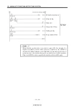
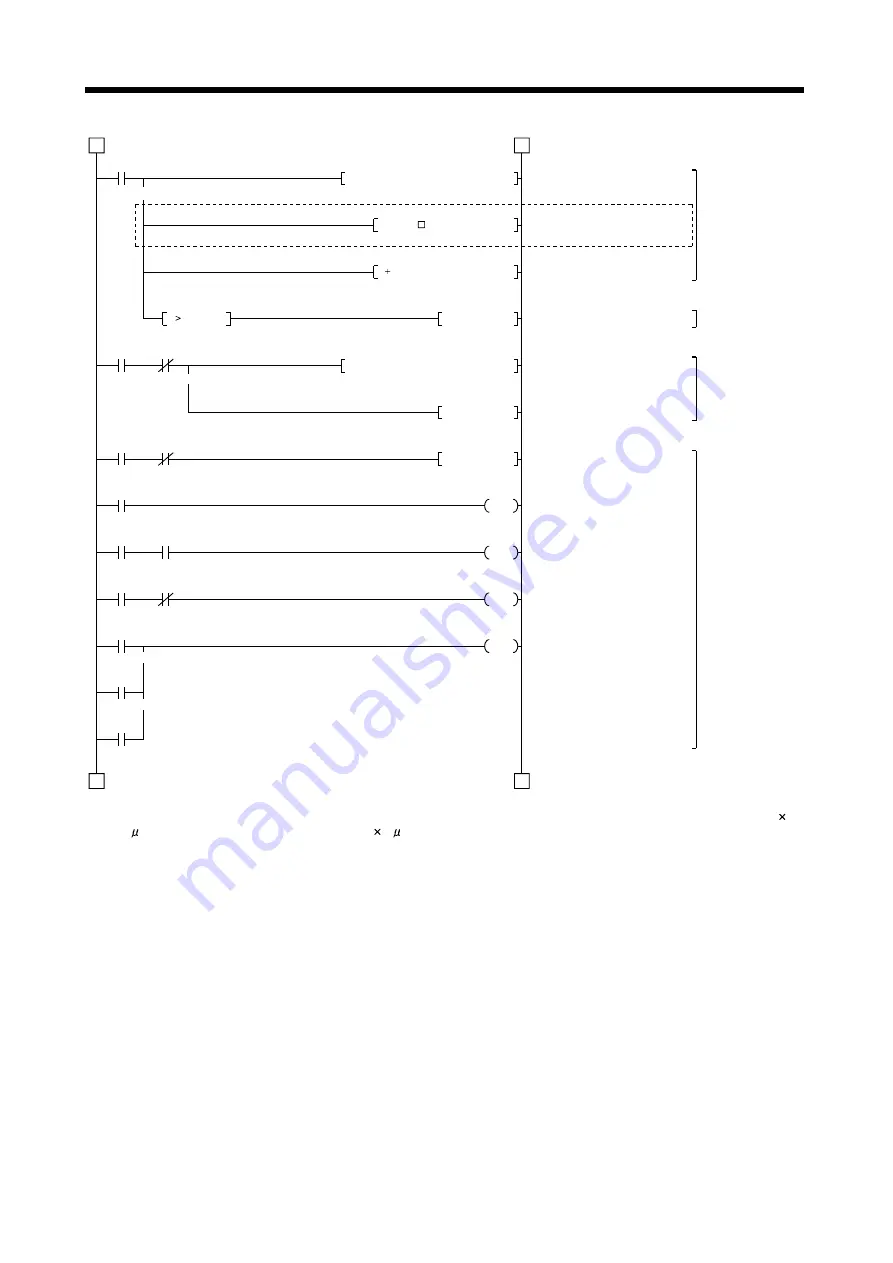
Note. When the unit setting parameter value of the A1SD71 positioning module is changed from "3" (pulse) to "0" (mm), the unit is
0.1 m for the input value. To change the unit to 1 m, and this program to multiple the feed value by 10.
Summary of Contents for MR-J2S-*A
Page 13: ...WWW NNC IR A 12 MEMO ...
Page 117: ...WWW NNC IR 3 70 3 SIGNALS AND WIRING MEMO ...
Page 185: ...WWW NNC IR 7 12 7 GENERAL GAIN ADJUSTMENT MEMO ...
Page 195: ...WWW NNC IR 8 10 8 SPECIAL ADJUSTMENT FUNCTIONS MEMO ...
Page 197: ...WWW NNC IR 9 2 9 INSPECTION MEMO ...
Page 221: ...WWW NNC IR 11 10 11 OUTLINE DIMENSION DRAWINGS MEMO ...
Page 293: ...WWW NNC IR 13 64 13 OPTIONS AND AUXILIARY EQUIPMENT MEMO ...
Page 321: ...WWW NNC IR 14 28 14 COMMUNICATION FUNCTIONS MEMO ...
Page 389: ...WWW NNC IR 15 68 15 ABSOLUTE POSITION DETECTION SYSTEM MEMO ...


