WWW.NNC.IR
15 - 59
15. ABSOLUTE POSITION DETECTION SYSTEM
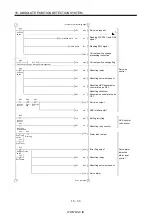
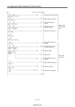
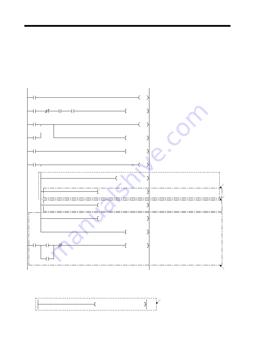
(f) Data set type home position return
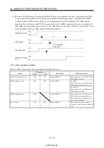
After jogging the machine to the position where the home position (e.g. 500) is to be set, choose the
home position return mode and set the home position with the home position return start switch
(X27) ON.
After switching power on, rotate the servo motor more than 1 revolution before starting home
position return.
Do not turn ON the clear (CR) (Y35) for an operation other than home position return. Turning it
on in other circumstances will cause position shift.
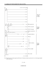
M9039
Y1D
Y31
X20
X27
M20
M21
T10
M20
PLS
M21
D9
K500
DMOVP
K1
D9
K72
H0000
DTOP
T10
M21
SET
K1
M21
RST
Y35
(Note 1)
17)
Programmable controller ready
Clear (CR) ON timer request
Clear (CR) 100ms ON timer
Setting data set type home position return request
Resetting data set type home position return
request
Switch clear (CR) on
Setting X-axis home position address 500
in data register
*1: Changing X-axis home position address
(Note 2)
PC RUN
Home position
return mode
ABS transfer
mode
Positioning
completion
Home position
return start switch
Clear signal ON
timer request
Data set type home position return request
Clear signal 100ms ON timer
Data set type home position
return request
K1
D9
K1154
H0000
DTOP
19)
18)
K1
K9003
K1150
H0000
TO
Y10
SET
X1
X4
Y10
Y10
RST
XA
*1: Changing X-axis current value
*1: Writing positioning data No. 9003
Starting positioning
Switching BUSY signal off to switch start
signal off.
Positioning
start
Start
completion
BUSY
Error detection
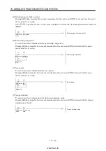
Note 1. When the data of the home position address parameter is not written from GX Developer or the like before starting the data set
type home position return program, this sequence circuit is required.
When the home position address is written in the home position address parameter, change to the following circuit.
K1
D9
K72
H0000
DFROP
17)
2. Changes are stored temporarily to buffer memory at this time. An additional processing is required when changes should be
reflected to memory for OS or flash ROM. For details, refer to the positioning module user's manual.
Summary of Contents for MR-J2S-*A
Page 13: ...WWW NNC IR A 12 MEMO ...
Page 117: ...WWW NNC IR 3 70 3 SIGNALS AND WIRING MEMO ...
Page 185: ...WWW NNC IR 7 12 7 GENERAL GAIN ADJUSTMENT MEMO ...
Page 195: ...WWW NNC IR 8 10 8 SPECIAL ADJUSTMENT FUNCTIONS MEMO ...
Page 197: ...WWW NNC IR 9 2 9 INSPECTION MEMO ...
Page 221: ...WWW NNC IR 11 10 11 OUTLINE DIMENSION DRAWINGS MEMO ...
Page 293: ...WWW NNC IR 13 64 13 OPTIONS AND AUXILIARY EQUIPMENT MEMO ...
Page 321: ...WWW NNC IR 14 28 14 COMMUNICATION FUNCTIONS MEMO ...
Page 389: ...WWW NNC IR 15 68 15 ABSOLUTE POSITION DETECTION SYSTEM MEMO ...


