WWW.NNC.IR
15 - 65
15. ABSOLUTE POSITION DETECTION SYSTEM
15.10 Absolute position data transfer errors
15.10.1 Corrective actions
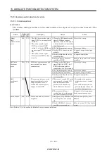
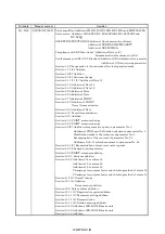
(1) Error list
The number within parentheses in the table indicates the output coil or input contact number of the
A1SD71.
Output coil
Name
AD71 1PG
Description
Cause
Action
1. Wiring for ABS transfer mode
signal, ABS data request
signal, or ready to send signal
is disconnected or connected to
the SG terminal.
Correct the wiring.
2. PLC ladder program wrong.
Correct the ladder.
3. Faulty PLC output or input
module.
Change the input or output
module.
4. Faulty printed board in the
servo amplifier.
Change the amplifier
(Note)
ABS
communication
error
Y49 Y11 1. The ABS data transfer mode
signal (Y41) is not completed
within 5s.
2. The ready to send signal
(X32) is not turned OFF
within 1s after the ABS data
request signal (Y42) is turned
ON.
3. The ready to send signal
(X32) remains OFF for longer
than 1s.
5. Power supply to the servo
amplifier is OFF.
Turn on the power to the servo
amplifier.
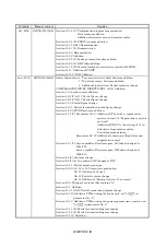
1. Wiring for the ABS data
signal (ABS bit 0 (PF), bit 1
(ZSP)) is disconnected or
connected to the SG terminal.
Correct the wiring.
2. PLC ladder program wrong.
Correct the ladder.
3. Faulty PLC input module.
Change the input module.
ABS data
checksum
error
Y4A Y12
ABS data sumcheck resulted
in mismatch four times
consecutively.
4. Faulty printed board in the
servo amplifier.
Change the amplifier.
1. The servo is turned ON or the
power supply is turned ON
near the machine home
position or in the zone in
which addresses decrease.
1. Reconsider the position
where the servo is turned
ON.
2. Set the home position for
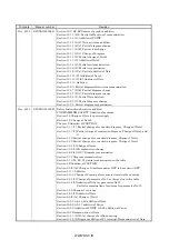
positioning apart from the
machine home position.
ABS
coordinate
error
Y4B
The motor position is in the
negative coordinate value
range when the servo is
turned ON or when power
supply is turned ON.
2. The machine falls on a
vertical axis when the servo-
on (SON) is turned ON/OFF.
Change the electromagnetic
brake operation sequence.
1. Emergency stop (EMG) of the
servo amplifier was turned
off.
After ensuring safety, turn
EMG on.
Servo alarm
Y48 Y10
Alarm occurred in the servo
amplifier.
2. Trouble (ALM) of the servo
amplifier was turned on.
Refer to section 10.2.2 and take
action.
Note. Refer to (2) in this section for details of error occurrence definitions.
Summary of Contents for MR-J2S-*A
Page 13: ...WWW NNC IR A 12 MEMO ...
Page 117: ...WWW NNC IR 3 70 3 SIGNALS AND WIRING MEMO ...
Page 185: ...WWW NNC IR 7 12 7 GENERAL GAIN ADJUSTMENT MEMO ...
Page 195: ...WWW NNC IR 8 10 8 SPECIAL ADJUSTMENT FUNCTIONS MEMO ...
Page 197: ...WWW NNC IR 9 2 9 INSPECTION MEMO ...
Page 221: ...WWW NNC IR 11 10 11 OUTLINE DIMENSION DRAWINGS MEMO ...
Page 293: ...WWW NNC IR 13 64 13 OPTIONS AND AUXILIARY EQUIPMENT MEMO ...
Page 321: ...WWW NNC IR 14 28 14 COMMUNICATION FUNCTIONS MEMO ...
Page 389: ...WWW NNC IR 15 68 15 ABSOLUTE POSITION DETECTION SYSTEM MEMO ...


