WWW.NNC.IR
3 - 41
3. SIGNALS AND WIRING
3.6.2 Detailed description of the interfaces
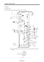
This section gives the details of the I/O signal interfaces (refer to I/O Division in the table) indicated in
sections 3.3.2.
Refer to this section and connect the interfaces with the external equipment.
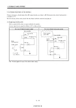
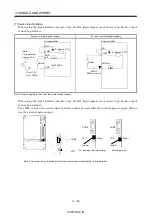
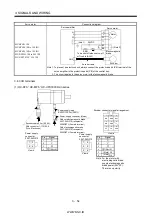
(1) Digital input interface DI-1
Give a signal with a relay or open collector transistor.
Source input is also possible. Refer to (7) in this section.
For use of internal power supply
For use of external power supply
VDD
COM
24VDC
SG
TR
Servo amplifier
R: Approx. 4.7
SON, etc.
(Note)
For a transistor
Approx. 5mA
V
CES
1.0V
I
CEO
100 A
Switch
COM
SG
Switch
SON, etc.
24VDC
200mA or more
Servo amplifier
R: Approx. 4.7
VDD
24VDC
Do not connect
VDD-COM.
Note. This also applies to the use of the external power supply.
Summary of Contents for MR-J2S-*A
Page 13: ...WWW NNC IR A 12 MEMO ...
Page 117: ...WWW NNC IR 3 70 3 SIGNALS AND WIRING MEMO ...
Page 185: ...WWW NNC IR 7 12 7 GENERAL GAIN ADJUSTMENT MEMO ...
Page 195: ...WWW NNC IR 8 10 8 SPECIAL ADJUSTMENT FUNCTIONS MEMO ...
Page 197: ...WWW NNC IR 9 2 9 INSPECTION MEMO ...
Page 221: ...WWW NNC IR 11 10 11 OUTLINE DIMENSION DRAWINGS MEMO ...
Page 293: ...WWW NNC IR 13 64 13 OPTIONS AND AUXILIARY EQUIPMENT MEMO ...
Page 321: ...WWW NNC IR 14 28 14 COMMUNICATION FUNCTIONS MEMO ...
Page 389: ...WWW NNC IR 15 68 15 ABSOLUTE POSITION DETECTION SYSTEM MEMO ...


