1
CONTENTS
1. FUNCTIONS AND CONFIGURATION
1 - 1 to 1 -28
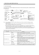
1.1 Overview................................................................................................................................................... 1 - 1
1.2 Control block diagram .............................................................................................................................. 1 - 2
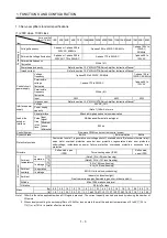
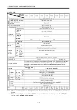
1.3 Servo amplifier standard specifications................................................................................................... 1 - 3
1.4 Function list .............................................................................................................................................. 1 - 5
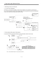
1.5 Selecting procedure of control mode....................................................................................................... 1 - 6
1.5.1 Control mode configuration............................................................................................................... 1 - 6
1.5.2 Dual feedback filter equivalent block diagram.................................................................................. 1 - 6
1.6 Model code definition ............................................................................................................................... 1 - 7
1.7 Combination with servo motor ................................................................................................................. 1 - 9
1.8 Structure .................................................................................................................................................. 1 -10
1.8.1 Parts identification ............................................................................................................................ 1 -10
1.8.2 Removal and reinstallation of the front cover.................................................................................. 1 -17
1.9 Configuration including auxiliary equipment .......................................................................................... 1 -20
1.10 System configuration ............................................................................................................................ 1 -28
2. SIGNALS AND WIRING
2 - 1 to 2 -18
2.1 Precautions for this chapter ..................................................................................................................... 2 - 2
2.2 Input power supply circuit ........................................................................................................................ 2 - 2
2.3 I/O signal connection example ............................................................................................................... 2 -13
2.4 Connector and signal arrangements ...................................................................................................... 2 -15
2.5 Internal connection diagram ................................................................................................................... 2 -16
2.6 Treatment of cable shield external conductor ........................................................................................ 2 -17
3. LOAD SIDE ENCODER
3 - 1 to 3 -32
3.1 Compatible linear encoder list ................................................................................................................. 3 - 1
3.2 Mitsubishi serial interface compatible linear encoder ............................................................................. 3 - 2
3.2.1
Linear scales manufactured by Mitutoyo Corporation (absolute type)............................................ 3 - 2
3.2.2
Linear encoder manufactured by Heidenhain Corporation............................................................. 3 -11
3.2.3
Linear encoder manufactured by Sony Manufacturing Systems Corporation (Incremental type) 3 -19
3.2.4 Linear encoder manufactured by Renishaw Inc. (Incremental type).............................................. 3 -24
3.3 ABZ-phase differential output load side encoder................................................................................... 3 -27
3.4 Mitsubishi optional cable connector sets.............................................................................................. 3 -30
3.4.1 MR-EKCBL M-H ............................................................................................................................ 3 -30
3.4.2 MR-ECNM ........................................................................................................................................ 3 -32
3.4.3 MR-J3CN2........................................................................................................................................ 3 -32
4. OPERATION AND FUNCTIONS
4 - 1 to 4 -22
4.1 Startup ...................................................................................................................................................... 4 - 1
4.1.1 Startup procedure.............................................................................................................................. 4 - 1
4.1.2 Selection of fully closed loop system................................................................................................ 4 - 2
4.1.3 Selection of load side encoder communication system................................................................... 4 - 3
4.1.4 Setting of load side encoder polarity ................................................................................................ 4 - 3
Summary of Contents for MR-J3-B-RJ006
Page 15: ...A 14 MEMO ...
Page 19: ...4 MEMO ...
Page 65: ...2 18 2 SIGNALS AND WIRING MEMO ...
Page 119: ...4 22 4 OPERATION AND FUNCTIONS MEMO ...
Page 145: ...6 6 6 TROUBLESHOOTING MEMO ...
Page 155: ...7 10 7 OUTLINE DRAWINGS MEMO ...
Page 165: ...SH NA 030056 C ...


