3 - 22
3. LOAD SIDE ENCODER
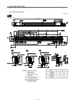
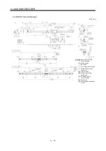
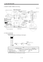
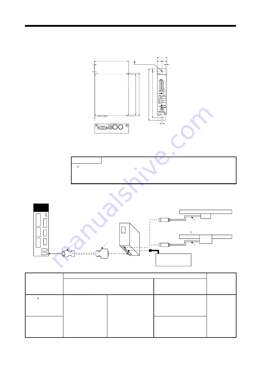
(d) MJ830/MJ831
[Unit: mm]
4.5 mounting hole
26
13
(13)
3
4.5
93
10
0
(11
5
)
13
8
12
4
1
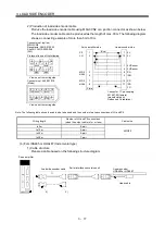
(4) Load side encoder
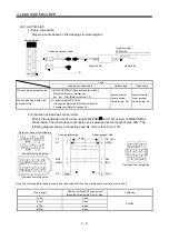
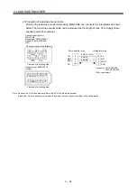
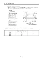
1) Cable structure
POINT
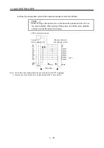
When turning on the power, turn on the interpolator and then turn on the
servo amplifier. When turning off the power, turn off the servo amplifier and
then turn off the interpolator.
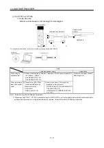
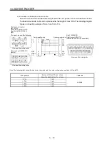
Prepare a cable based on the following structure diagram.
Linear encoder SH13
Servo amplifier
CN2L
1)
Interpolator
MJ830 or MJ831
Linear encoder
SL710 PL101-R/RH
SL710
PL101-
R/RH
2)
Head cable
Stabilized power supply
5V (MJ830)
12 to 14V (MJ831)
Head cable
Cable
Linear encoder
Load side encoder cable (Note)
Head cable
Interpolator
(This should be
prepared by the
customer.)
SL710 PL101-R/RH Accessories
for
linear
encoder
Cable Length
PL101-R: 0.3m
PL101-RH: 3m
SH13
1) Connector set
MR-J3CN2
(Option manufactured
by Mitsubishi Electric
Corporation)
(Refer to section 3.4.)
2) Connector for
Interpolator
(This should be prepared
by the customer.)
Connector: 10114-
3000PE
Shell kit: 10314-52F0-
008 (3M or equivalent)
Accessories for linear encoder
Cable length: 1m
MJ830 or MJ831
Note. Produce an encoder cable. An optional cable is not provided.
Summary of Contents for MR-J3-B-RJ006
Page 15: ...A 14 MEMO ...
Page 19: ...4 MEMO ...
Page 65: ...2 18 2 SIGNALS AND WIRING MEMO ...
Page 119: ...4 22 4 OPERATION AND FUNCTIONS MEMO ...
Page 145: ...6 6 6 TROUBLESHOOTING MEMO ...
Page 155: ...7 10 7 OUTLINE DRAWINGS MEMO ...
Page 165: ...SH NA 030056 C ...

