


10. CHARACTERISTICS
10 - 9
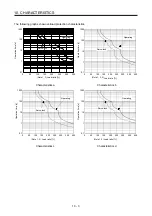
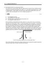
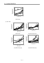
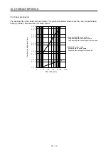
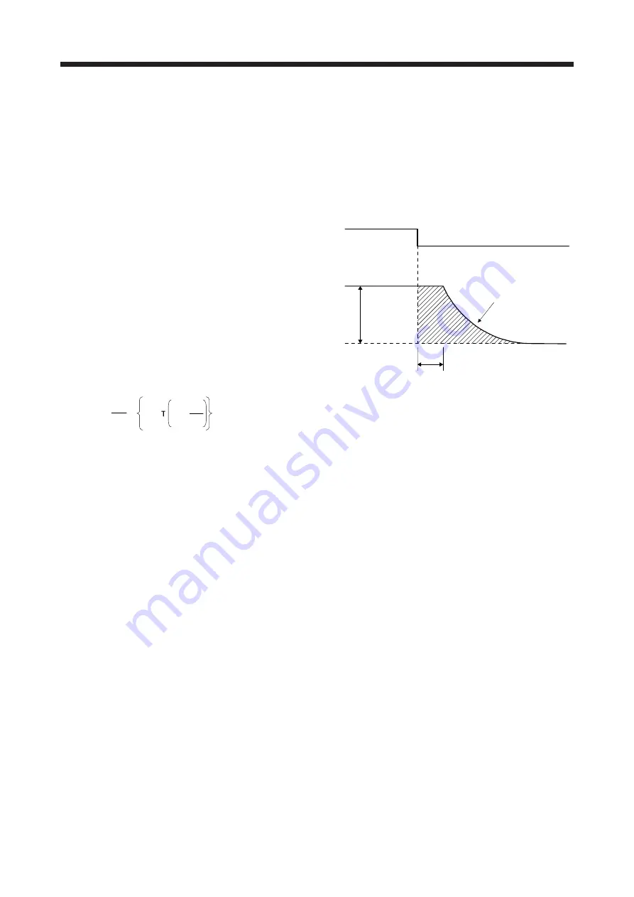
10.3.1 Dynamic brake operation
(1) Calculation of coasting distance
Fig. 10.3 shows the pattern in which the servo motor comes to a stop when the dynamic brake is
operated. Use equation 10.2 to calculate an approximate coasting distance to a stop. The dynamic
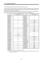
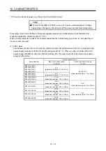
brake time constant
τ
varies with the servo motor and machine operation speeds. (Refer to (2) (a), (b) in
this section.)
A working part generally has a friction force. Therefore, actual coasting distance will be shorter than a
maximum coasting distance calculated with the following equation.
V
0
OFF
ON
Machine speed
t
e
Time
EM1 (Forced stop 1)
Dynamic brake
time constant
τ
Fig. 10.3 Dynamic brake operation diagram
L
max
=
60
V
0
•
t
e
+
J
M
1 + J
L
··························································································· (10.2)
L
max
: Maximum coasting distance ····················································································· [mm]
V
0
: Machine's fast feed speed ····················································································· [mm/min]
J
M
: Moment of inertia of the servo motor ·································································· [× 10
-4
kg•m
2
]
J
L
: Load moment of inertia converted into equivalent value on servo motor shaft ·············· [× 10
-4
kg•m
2
]
τ
: Dynamic brake time constant ···························································································· [s]
t
e
: Delay time of control section ···························································································· [s]
For 7 kW or lower servo amplifier, there is internal relay delay time of about 10 ms. For 11 kW to 22
kW servo amplifier, there is delay caused by magnetic contactor built into the external dynamic brake
(about 50 ms) and delay caused by the external relay.
Summary of Contents for MR-J4-100A(-RJ)
Page 19: ...10 MEMO ...
Page 75: ...1 FUNCTIONS AND CONFIGURATION 1 56 MEMO ...
Page 83: ...2 INSTALLATION 2 8 MEMO ...
Page 159: ...3 SIGNALS AND WIRING 3 76 MEMO ...
Page 203: ...4 STARTUP 4 44 MEMO ...
Page 351: ...7 SPECIAL ADJUSTMENT FUNCTIONS 7 40 MEMO ...
Page 365: ...8 TROUBLESHOOTING 8 14 MEMO ...
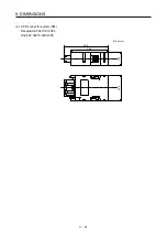
Page 387: ...9 DIMENSIONS 9 22 MEMO ...
Page 403: ...10 CHARACTERISTICS 10 16 MEMO ...
Page 553: ...12 ABSOLUTE POSITION DETECTION SYSTEM 12 30 MEMO ...
Page 567: ...13 USING STO FUNCTION 13 14 MEMO ...
Page 607: ...14 COMMUNICATION FUNCTION MITSUBISHI ELECTRIC GENERAL PURPOSE AC SERVO PROTOCOL 14 40 MEMO ...
Page 639: ...15 USING A LINEAR SERVO MOTOR 15 32 MEMO ...
Page 767: ...18 MR J4 03A6 RJ SERVO AMPLIFIER 18 84 MEMO ...
Page 856: ...APPENDIX App 41 ...
Page 905: ...MEMO ...


