

11. OPTIONS AND PERIPHERAL EQUIPMENT
11 - 41
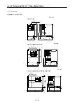
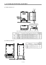
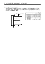
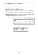
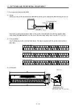
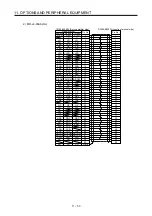
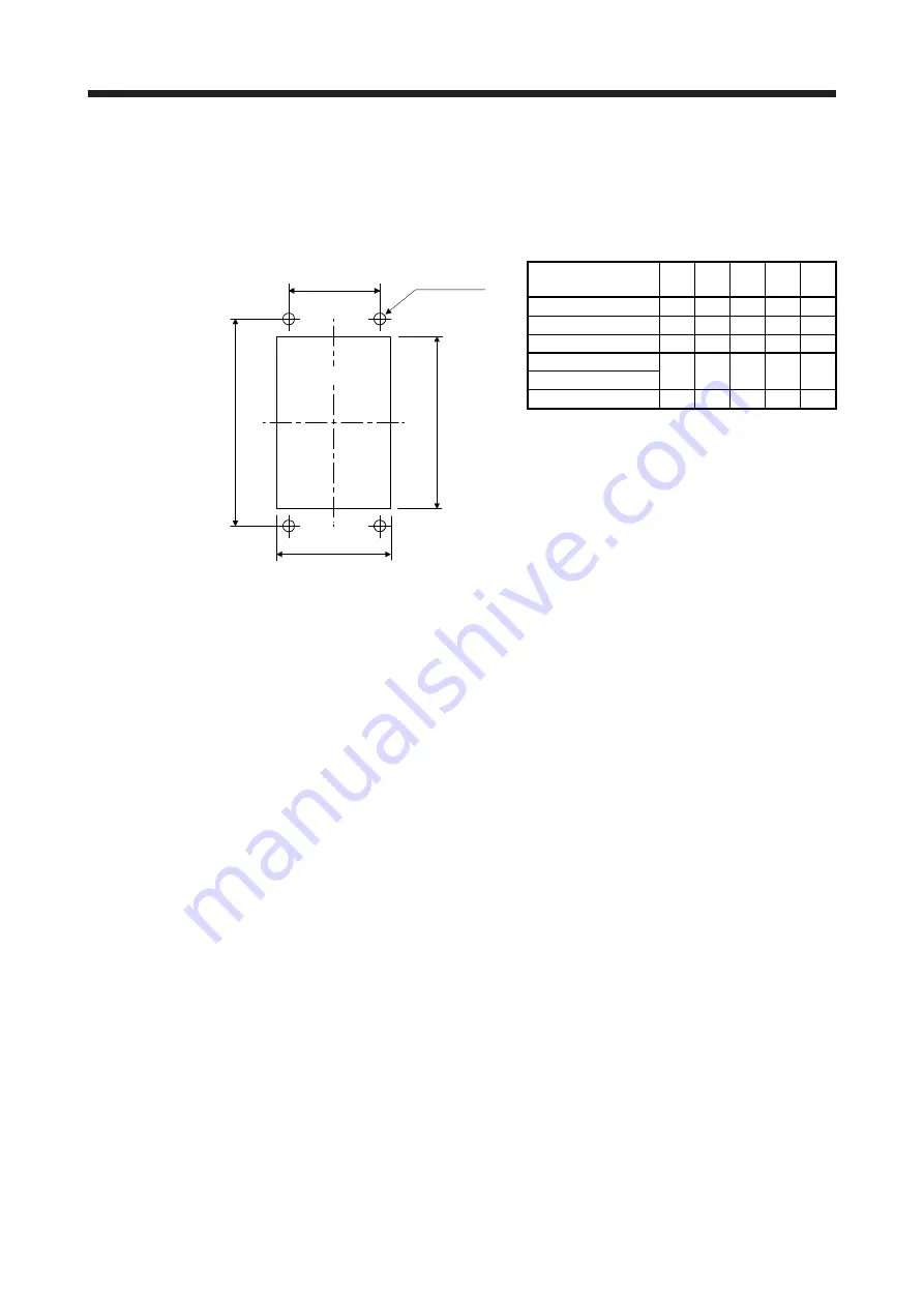
(4) Mounting hole machining dimensions
The following shows mounting hole dimensions for mounting the heat generation area of the power
regeneration converter outside a cabinet as measures against heat generation when the converter is
mounted in an enclosed type cabinet.
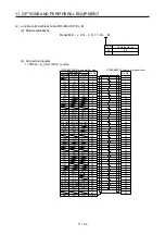
[Unit: mm]
(AA)
(BA)
b
a
(2-
φ
D hole)
(Mounting hole)
Power regeneration
converter
a b D AA
BA
FR-RC-15K 260
412
10
200
432
FR-RC-30K 330
562
10
270
582
FR-RC-55K 470
642
12
410
670
FR-RC-H15K
330 562 10 270 582
FR-RC-H30K
FR-RC-H55K 470
642
12
410
670
Summary of Contents for MR-J4-100A(-RJ)
Page 19: ...10 MEMO ...
Page 75: ...1 FUNCTIONS AND CONFIGURATION 1 56 MEMO ...
Page 83: ...2 INSTALLATION 2 8 MEMO ...
Page 159: ...3 SIGNALS AND WIRING 3 76 MEMO ...
Page 203: ...4 STARTUP 4 44 MEMO ...
Page 351: ...7 SPECIAL ADJUSTMENT FUNCTIONS 7 40 MEMO ...
Page 365: ...8 TROUBLESHOOTING 8 14 MEMO ...
Page 387: ...9 DIMENSIONS 9 22 MEMO ...
Page 403: ...10 CHARACTERISTICS 10 16 MEMO ...
Page 553: ...12 ABSOLUTE POSITION DETECTION SYSTEM 12 30 MEMO ...
Page 567: ...13 USING STO FUNCTION 13 14 MEMO ...
Page 607: ...14 COMMUNICATION FUNCTION MITSUBISHI ELECTRIC GENERAL PURPOSE AC SERVO PROTOCOL 14 40 MEMO ...
Page 639: ...15 USING A LINEAR SERVO MOTOR 15 32 MEMO ...
Page 767: ...18 MR J4 03A6 RJ SERVO AMPLIFIER 18 84 MEMO ...
Page 856: ...APPENDIX App 41 ...
Page 905: ...MEMO ...


