
18. MR-J4-03A6(-RJ) SERVO AMPLIFIER
18 - 41
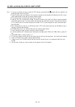
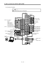
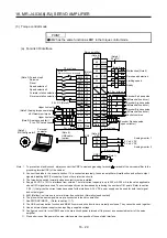
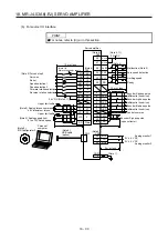
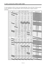
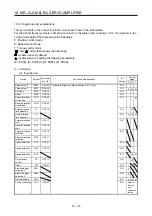
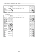
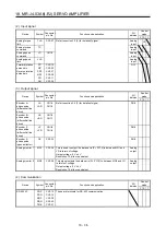
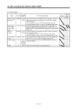
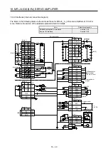
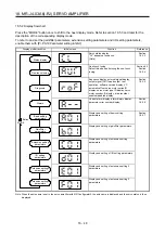
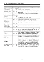
Note 1. P: position control mode, S: speed control mode, T: torque control mode
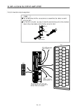
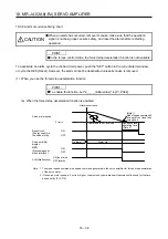
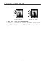
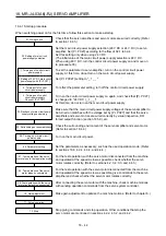
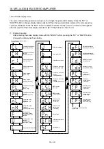
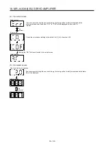
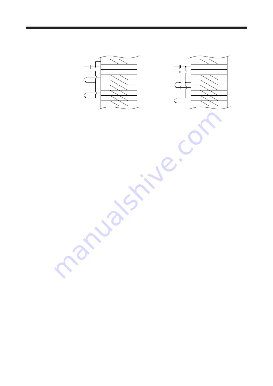
2. This is for the differential line driver pulse train input. For the open-collector pulse train input, connect as follows.
DOCOM
46
OPC
12
20
47
PP
10
PG
11
NP
35
NG
36
DICOM
DOCOM
PP2
37
NP2
38
24 V DC
DOCOM
46
OPC
12
20
47
PP
10
PG
11
NP
35
NG
36
DICOM
DOCOM
PP2
37
NP2
38
24 V DC
For sink input interface
For source input interface
3. This diagram shows sink I/O interface. For source I/O interface, refer to section 3.9.3.
4. The illustration of the 24 V DC power supply is divided between input signal and output signal for convenience. However, they
can be configured by one.
For 24 V DC power for I/O signal, use power other than 24 V DC power of servo amplifier control circuit power supply.
5. To use the RS-422 communication function, connect between TRE and RDN of the final axis servo amplifier. (Refer to section
18.11.)
Summary of Contents for MR-J4-100A(-RJ)
Page 19: ...10 MEMO ...
Page 75: ...1 FUNCTIONS AND CONFIGURATION 1 56 MEMO ...
Page 83: ...2 INSTALLATION 2 8 MEMO ...
Page 159: ...3 SIGNALS AND WIRING 3 76 MEMO ...
Page 203: ...4 STARTUP 4 44 MEMO ...
Page 351: ...7 SPECIAL ADJUSTMENT FUNCTIONS 7 40 MEMO ...
Page 365: ...8 TROUBLESHOOTING 8 14 MEMO ...
Page 387: ...9 DIMENSIONS 9 22 MEMO ...
Page 403: ...10 CHARACTERISTICS 10 16 MEMO ...
Page 553: ...12 ABSOLUTE POSITION DETECTION SYSTEM 12 30 MEMO ...
Page 567: ...13 USING STO FUNCTION 13 14 MEMO ...
Page 607: ...14 COMMUNICATION FUNCTION MITSUBISHI ELECTRIC GENERAL PURPOSE AC SERVO PROTOCOL 14 40 MEMO ...
Page 639: ...15 USING A LINEAR SERVO MOTOR 15 32 MEMO ...
Page 767: ...18 MR J4 03A6 RJ SERVO AMPLIFIER 18 84 MEMO ...
Page 856: ...APPENDIX App 41 ...
Page 905: ...MEMO ...


