4. STARTUP
4 - 6
4.1.3 Surrounding environment
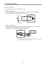
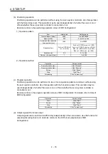
(1) Cable routing
(a) The wiring cables should not be stressed.
(b) The encoder cable should not be used in excess of its bending life. (Refer to section 10.4.)
(c) The connector of the servo motor should not be stressed.
(2) Environment
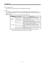
Signal cables and power cables are not shorted by wire offcuts, metallic dust or the like.
4.2 Startup
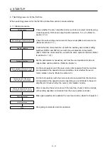
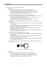
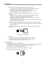
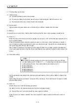
Connect the servo motor with a machine after confirming that the servo motor operates properly alone.
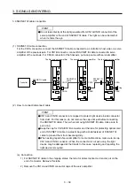
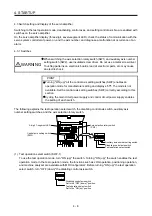
(1) Power on
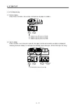
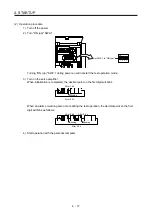
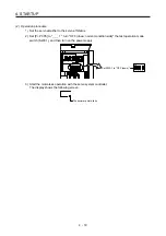
When the main and control circuit power supplies are turned on, "b01" (for the first axis) appears on the
servo amplifier display.
When the absolute position detection system is used in a rotary servo motor, first power-on results in
[AL. 25 Absolute position erased] and the servo-on cannot be ready. The alarm can be deactivated by
then switching power off once and on again.
Also, if power is switched on at the servo motor speed of 3000 r/min or higher, position mismatch may
occur due to external force or the like. Power must therefore be switched on when the servo motor is at
a stop.
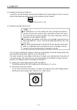
(2) Parameter setting
POINT
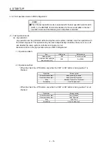
The following encoder cables are of four-wire type. When using any of these
encoder cables, set [Pr. PC04] to "1 _ _ _" to select the four-wire type. Incorrect
setting will result in [AL. 16 Encoder initial communication error 1].
MR-EKCBL30M-L
MR-EKCBL30M-H
MR-EKCBL40M-H
MR-EKCBL50M-H
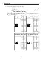
Set the parameters according to the structure and specifications of the machine. Refer to chapter 5 for
details.
After setting the above parameters, turn power off as necessary. Then switch power on again to enable
the parameter values.
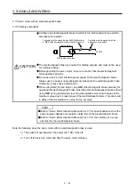
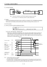
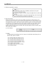
(3) Servo-on
Enable the servo-on with the following procedure.
(a) Switch on main circuit power supply and control circuit power supply.
(b) Transmit the servo-on command with the servo system controller.
When the servo-on status is enabled, the servo amplifier is ready to operate and the servo motor is
locked.
Summary of Contents for MR-J4-100B(-RJ)
Page 17: ...8 MEMO ...
Page 143: ...4 STARTUP 4 20 MEMO ...
Page 199: ...5 PARAMETERS 5 56 MEMO ...
Page 227: ...6 NORMAL GAIN ADJUSTMENT 6 28 MEMO ...
Page 281: ...8 TROUBLESHOOTING 8 16 MEMO ...
Page 303: ...9 DIMENSIONS 9 22 MEMO ...
Page 319: ...10 CHARACTERISTICS 10 16 MEMO ...
Page 429: ...11 OPTIONS AND PERIPHERAL EQUIPMENT 11 110 MEMO ...
Page 435: ...12 ABSOLUTE POSITION DETECTION SYSTEM 12 6 MEMO ...
Page 483: ...14 USING A LINEAR SERVO MOTOR 14 34 MEMO ...
Page 531: ...16 FULLY CLOSED LOOP SYSTEM 16 26 MEMO ...
Page 613: ...17 APPLICATION OF FUNCTIONS 17 82 MEMO ...
Page 654: ...APPENDIX App 41 ...

