5. PARAMETERS
5 - 51
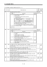
5.2.6 Extension setting 3 parameters ([Pr. PF_ _ ])
No.
Symbol
Name and function
Initial
value
[unit]
Setting
range
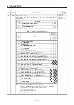
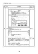
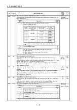
PF06
*FOP5 Function selection F-5
Refer to the
"Name and
function" column.
Setting
digit
Explanation
Initial
value
_ _ _ x
Electronic dynamic brake selection
0: Automatic (enabled only for specified servo motors)
2: Disabled
Refer to the following table for the specified servo motors.
0h
Series
Servo
motor
HG-KR HG-KR053/HG-KR13/HG-KR23/HG-KR43
HG-MR
HG-MR053/HG-MR13/HG-MR23/HG-MR43
HG-SR HG-SR51/HG-SR52
_ _ x _
For manufacturer setting
0h
_ x _ _
0h
x _ _ _
0h
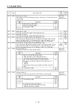
PF12 DBT Electronic
dynamic brake operating time
Set an operating time for the electronic dynamic brake.
2000
[ms]
0 to
10000
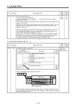
PF18 **STOD STO
diagnosis
error detection time
Set the time from when an error occurs in the STO input signal or STO circuit until the
detection of [AL. 68.1 Mismatched STO signal error].
When 0 s is set, the detection of [AL. 68.1 Mismatched STO signal error] is not performed.
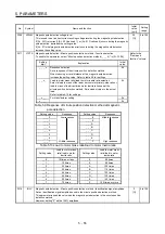
The following shows safety levels at the time of parameter setting.
0
[s]
0
to
60
Setting
value
STO input diagnosis by
TOFB output
Safety level
0
Execute
EN ISO 13849-1 Category 3 PL d, IEC 61508
SIL 2, EN 62061 SIL CL2
Not
execute
1 to 60
Execute
EN ISO 13849-1 Category 3 PL e, IEC 61508
SIL 3, and EN 62061 SIL CL3
Not execute
EN ISO 13849-1 Category 3 PL d, IEC 61508
SIL 2, and EN 62061 SIL CL2
When the short-circuit connector is connected to the CN8 connector, set "0" in the parameter.
When MR-D30 functional safety unit is used, the parameter is not available.
For safety levels at the time of using MR-D30, refer to "MR-D30 Instruction Manual".
This parameter is available with servo amplifiers with software version C1 or later.
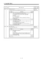
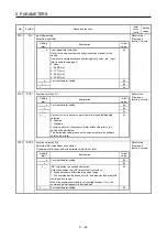
PF21
DRT
Drive recorder switching time setting
This is used to set a drive recorder switching time.
When a USB communication is cut during using a graph function, the function will be changed
to the drive recorder function after the setting time of this parameter.
When a value from "1" to "32767" is set, it will switch after the setting value.
However, when "0" is set, it will switch after 600 s.
When "-1" is set, the drive recorder function is disabled.
0
[s]
-1 to
32767
Summary of Contents for MR-J4-100B(-RJ)
Page 17: ...8 MEMO ...
Page 143: ...4 STARTUP 4 20 MEMO ...
Page 199: ...5 PARAMETERS 5 56 MEMO ...
Page 227: ...6 NORMAL GAIN ADJUSTMENT 6 28 MEMO ...
Page 281: ...8 TROUBLESHOOTING 8 16 MEMO ...
Page 303: ...9 DIMENSIONS 9 22 MEMO ...
Page 319: ...10 CHARACTERISTICS 10 16 MEMO ...
Page 429: ...11 OPTIONS AND PERIPHERAL EQUIPMENT 11 110 MEMO ...
Page 435: ...12 ABSOLUTE POSITION DETECTION SYSTEM 12 6 MEMO ...
Page 483: ...14 USING A LINEAR SERVO MOTOR 14 34 MEMO ...
Page 531: ...16 FULLY CLOSED LOOP SYSTEM 16 26 MEMO ...
Page 613: ...17 APPLICATION OF FUNCTIONS 17 82 MEMO ...
Page 654: ...APPENDIX App 41 ...

