11. OPTIONS AND PERIPHERAL EQUIPMENT
11 - 12
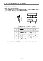
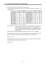
11.2.2 Selection of regenerative option
(1) Rotary servo motor and direct drive motor
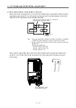
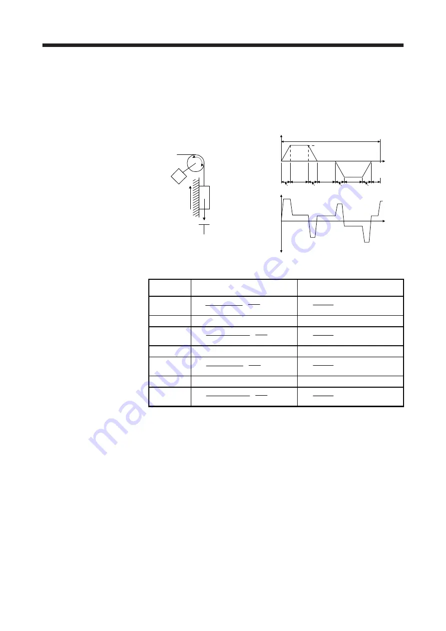
Use the following method when regeneration occurs continuously in vertical motion applications or when
it is desired to make an in-depth selection of the regenerative option.
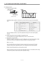
(a) Regenerative energy calculation
M
Friction
torque
U
nbalanced tor
que
T
F
T
U
Ser
vo motor
speed
Gener
ated tor
que
Time
Up
V
tf (1 cycle)
Down
(+)
(-)
(Power running)
(Regeneration)
t
psd2
t
2
t
3
t
4
t
1
t
psa2
t
psd1
t
psa1
1)
2)
3)
4)
5)
6)
7)
8)
Formulas for calculating torque and energy in operation
Regenerative
power
Torque applied to servo motor [N•m]
(Note)
Energy E [J]
1)
T
1
=
(J
L
/
η
+ J
M
) • V
9.55 • 10
4
•
t
psa1
1
+ T
U
+ T
F
E
1
=
2
0.1047
• V • T
1
• t
psa1
2) T
2
= T
U
+ T
F
E
2
= 0.1047 • V • T
2
• t
1
3)
T
3
=
-(J
L
•
η
+ J
M
) • V
9.55 • 10
4
•
t
psd1
1
+ T
U
+ T
F
E
3
=
2
0.1047
• V • T
3
• t
psd1
4), 8)
T
4,
T
8
= T
U
E
4
, E
8
≥
0 (No regeneration)
5)
T
5
=
(J
L
/
η
+ J
M
) • V
9.55 • 10
4
•
t
psa2
1
- T
U
+ T
F
E
5
=
2
0.1047
• V • T
5
• t
psa2
6) T
6
= -T
U
+ T
F
E
6
= 0.1047 • V • T
6
• t
3
7)
T
7
=
-(J
L
•
η
+ J
M
) • V
9.55 • 10
4
•
t
psd2
1
- T
U
+ T
F
E
7
=
2
0.1047
• V • T
7
• t
psd2
Note.
η
: Drive system efficiency
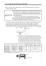
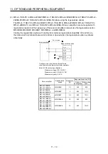
From the calculation results in 1) to 8), find the absolute value (Es) of the sum total of negative
energies.
Summary of Contents for MR-J4-100B(-RJ)
Page 17: ...8 MEMO ...
Page 143: ...4 STARTUP 4 20 MEMO ...
Page 199: ...5 PARAMETERS 5 56 MEMO ...
Page 227: ...6 NORMAL GAIN ADJUSTMENT 6 28 MEMO ...
Page 281: ...8 TROUBLESHOOTING 8 16 MEMO ...
Page 303: ...9 DIMENSIONS 9 22 MEMO ...
Page 319: ...10 CHARACTERISTICS 10 16 MEMO ...
Page 429: ...11 OPTIONS AND PERIPHERAL EQUIPMENT 11 110 MEMO ...
Page 435: ...12 ABSOLUTE POSITION DETECTION SYSTEM 12 6 MEMO ...
Page 483: ...14 USING A LINEAR SERVO MOTOR 14 34 MEMO ...
Page 531: ...16 FULLY CLOSED LOOP SYSTEM 16 26 MEMO ...
Page 613: ...17 APPLICATION OF FUNCTIONS 17 82 MEMO ...
Page 654: ...APPENDIX App 41 ...

